INFORMATION FOR REPLACING THE
FUNCTIONAL UNITS
6
63
EN
5. With reference
X
pointed upwards, find the
TDC through tool
ST_30,
then bring the dial
gauge indicator to 0.
6. H
aving identified the value to lower the piston,
rotate the crankshaft anti-clockwise by goin
g
beyond the value described in
Tab. 6.1
, once
ag
ain, rotate the crankshaft clockwise,
stopping at the correct advance value by using
tool
ST_30
7. Lo
ck the
ST_34
t
ool through
J
screws and
ensure that the crankshaft does not rotate,
which would alter the correct advance value. I
f
thi
s happens, repeat the instructions described
in points
4, 5, 6, 7 and 8.
NOTE:
The value indicated in
Tab. 6.1
must be
reached by rotating the shaft with the piston in
compression phase. Use the
ST_34
tool to totate
the crankshaft.
Fig 6.12
8. Lock the
ST_34
tool through
J
screws and
ensure that the crankshaft does not rotate,
which would alter the correct advance value. I
f
thi
s happens, repeat the instructions described
in points
4, 5, 6, 7 and 8
.
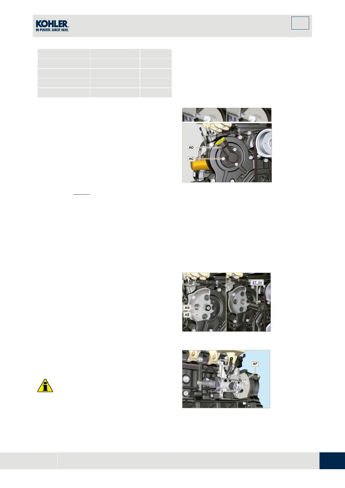
9. Undo the screws
AC
and remove the oil filling
flange
AD
.
10. Undo and remove the nut
AN
fixing the
injection pump control gear
AE
.
11. U
ndo the capscrew
K
and shift the slotted
plate
AB
in the direction of arrow
AA
.
12. T
ighten screw
K
to block the pump (tightening
torque to
12
Nm
).
Important
•
After removing the nut AN, ensure that the
correct advance value has remained
Fig 6.13
Fig 6.14

 Loading...


