11.1.4 Expansion card -SERCOS-
This section describes the sercos
®
II expansion card for S700. Information on the range of
functions and the software protocol can be found in our manual “IDN Reference Guide
sercos
®
”.
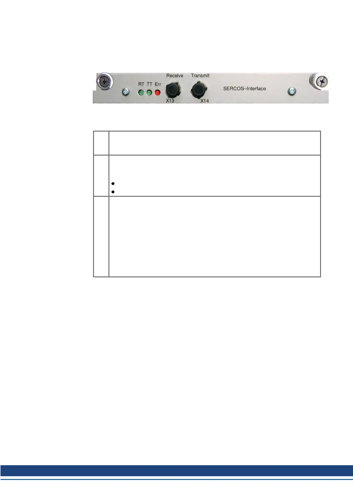
11.1.4.1 LEDs
RT
Indicates whether sercos
®
telegrams are being correctly received. In the final Com-
munication Phase 4 this LED should flicker, since cyclical telegrams are being
received.
TT
Indicates that sercos
®
telegrams are being transmitted. In the final Com-
munication Phase 4 this LED should flicker, since cyclical telegrams are being
transmitted. Check the station addresses for the controls and the servo amplifier if:
- the LED never lights up in sercos
®
Phase 1 or
- the axis cannot be operated, although the RT LED is lighting up cyclically.
ERR
Indicates that sercos
®
communication is faulty or suffering from interference.
If this LED is very bright, then communication is suffering strong interference, or is
non-existent. Check the sercos
®
transmission speed for the controls and the servo
amplifier (BAUD RATE) and the fiber-optic connection.
If this LED fades or flickers, this indicates a low level of interference for sercos
®
communication, or the optical transmitting power is not correctly matched to the
length of cable. Check the transmitting power of the (physically) previous sercos
®
station. The transmitting power of the servo amplifier can be adjusted in the setup
software DRIVEGUI.EXE on the sercos
®
screen page, by altering the length para-
meter for the cable length.
11.1.4.2 Connection technology
For the fiber optic cable connection, only use sercos
®
components to the sercos
®
Standard
IEC 61491.
Receive data
The fiber optic cable carrying receive data for the drive in the ring structure is connected to
X13 with an F-SMA connector.
Transmit data
Connect the fiber optic cable for the data output to X14 by F-SMA connector.
S748-772 Instructions Manual | 11 Expansions
Kollmorgen | kdn.kollmorgen.com | July 2019 131
 Loading...


