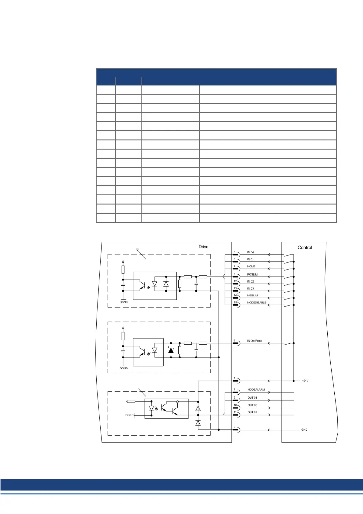
11.1.6.4 Digital inputs and outputs, connector X21A (SubD 15-pin, socket)
Inputs (In): 24V (20...28V), opto-isolated, one high-speed input (Pin 4)
Outputs (Out): 24V, opto-isolated, Darlington driver
Pinout connector X21A (SubD 15 pin)
Pin Type Description
1 In +24V power supply
2 Out NODEALARM indicates a problem with the node
3 Out OUT_01 digital output
4 In IN_00 (fast) capture input (fast)
5 In IN_04 digital input
6 In IN_01 digital input
7 In HOME reference switch
8 In POSLIM limit switch, positive direction
9 In GND power supply
10 Out OUT_00 digital output
11 Out OUT_02 digital output
12 In IN_02 digital input
13 In IN_03 digital input
14 In NEGLIM limit switch, negative direction
15 In NODEDISABLE disables Node
11.1.6.5 Connection diagram digital inputs and outputs, connector X21A
S748-772 Instructions Manual | 11 Expansions
Kollmorgen | kdn.kollmorgen.com | July 2019 137
 Loading...


