7.2.7 Conductor cross-sections
Recommendations for cables (material and construction (➜ # 63).
Following IEC 60204 (B2), we recommend for single-axis systems:
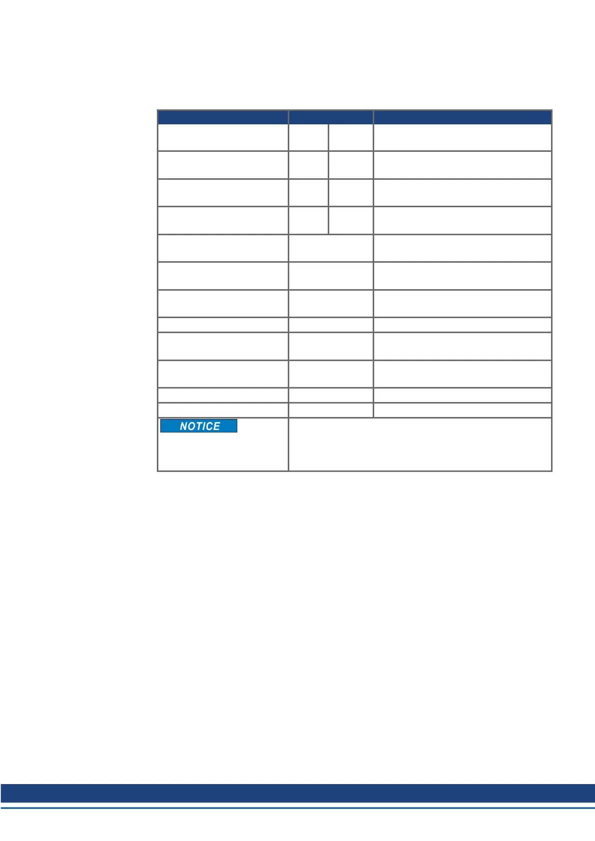
Interface Cross section Techn. requirements
AC connection S748:
S772:
16 mm²
25 mm²
600 V, 80°C
DC bus link S748:
S772:
25 mm²
25 mm²
1000 V, 80°C, shielded
for lengths >0.50 m
Brake resistor S748:
S772:
35 mm²
35 mm²
1000 V, 80°C, shielded
for lengths >0.50 m
Motor cables S748:
S772:
16 mm²
25 mm²
600 V, 80°C, shielded,
capacitance <150 pF/m
Resolver, motor thermal con-
trol, max.100m*
4x2x0.25 mm² twisted pairs, shielded, C<120 pF/m
Encode, rmotor thermal con-
trol, max. 50m*
7x2x0.25 mm² twisted pairs, shielded, C<120 pF/m
ComCoder, motor thermal
control, max. 25m
8x2x0.25 mm² twisted pairs, shielded, C<120 pF/m
Setpoints, AGND, max 30m 0.25 mm² twisted pairs, shielded
Control signals, BTB,
DGND, max. 30m
0.5 mm²
Holding brake (motor) min. 0.75 mm² 600 V, 80°C, shielded,
check voltage drop
+24 V electronics, max 30m max. 1.5 mm² check voltage drop
+24 V motor brake, max 30m max. 1.5 mm² check voltage drop
For multi-axis systems, observe the specific operating con-
ditions for your system.
To reach functional safety with the max. permitted cable
length, observe cable requirements (➜ # 63)
* Kollmorgen North America supplies cables up to 39 meters, Europe up to max. length
S748-772 Instructions Manual | 7 Technical description
Kollmorgen | kdn.kollmorgen.com | July 2019 33
 Loading...


