9.13.2 Connection to stepper motor controllers (step and direction)
You can connect the servo amplifier to a third-party stepper-motor controller. Parameter set-
ting for the slave amplifier is carried out with the aid of the setup software (electronic gear-
ing). The number of steps can be adjusted, so that the servo amplifier can be adapted to
match the step-direction signals of any stepper controller. Various monitoring signals can be
generated.
Using an A quad B encoder provides better EMC noise immunity.
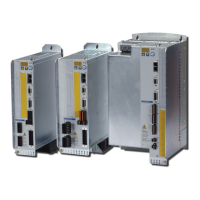
9.13.2.1 Step / Direction with 5 V signal level (X1)
Wiring of the servo amplifier (SubD connector X1) to a stepper-motor controller with a 5V sig-
nal level.
Frequency limit: 1.5 MHz
Control GEARMODE
Step/direction 5V 27
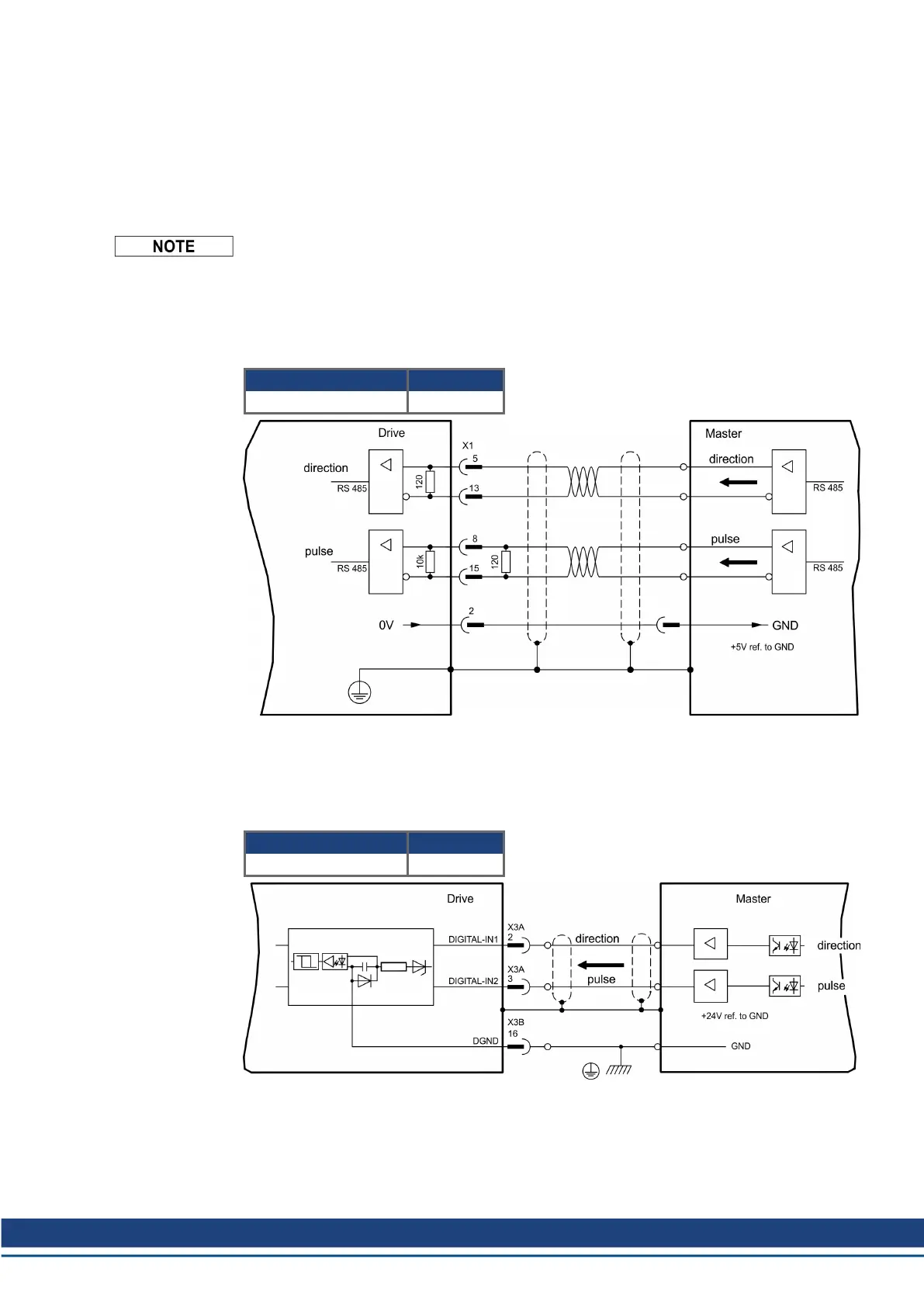
9.13.2.2 Step / Direction with 24 V signal level (X3)
Wiring of the servo amplifier to a stepper-motor controller with a 24 V signal level. The digital
inputs DIGITAL-IN 1 and 2 on connector X3 are used.
Frequency limit: 100 kHz
Control GEARMODE
Step/direction 24V 1
S748-772 Instructions Manual | 9 Electrical Installation
Kollmorgen | kdn.kollmorgen.com | July 2019 95
 Loading...


