S748-772 Instructions Manual | 9 Electrical Installation
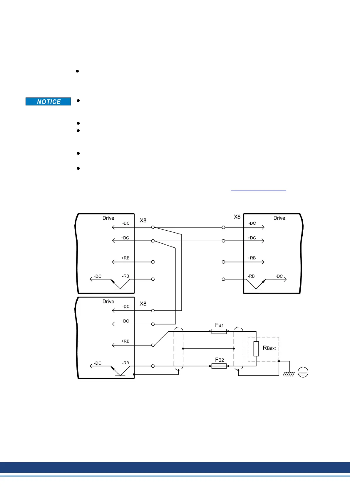
9.9 DC bus link (X8)
Terminals X8/-DC and X8/+RBe. Can be connected in parallel, whereby the brake power is
divided between all the amplifiers that are connected to the same DC bus link circuit.
Screw driver for plus-minus-screws (Combiprofile Slotted/Pozidriv) size 2
In case of mains supply from the same mains (identical mains supply voltage) three servo
amplifiers S748/772 may be connected by the DC bus link.
The servo amplifiers can be destroyed, if DC bus link voltages are different. Only servo
amplifiers with mains supply from the same mains (identical mains supply voltage) may
be connected by the DC bus link.
VBUSBAL must be identical with all devices on the same DC bus.
The sum of the rated currents for all of the servo amplifiers connected in parallel to an
S748/772 must not exceed 96 Arms (140 Apeak).
Examples: S748-S748-S748 oder S772-S748 oder S772-S772
Use unshielded single cores with a max. length of 500mm (cross reference see (➜ #
33)); use shielded cables for longer lengths.
Servo amplifiers working generatively very often, should be placed beside amplifiers,
which need energy. That reduces current flow on longer distances.
Fusing information are explained in detail in the KDN on page "DC Bus link in parallel".
Wiring example with external brake resistor
70 Kollmorgen | kdn.kollmorgen.com | July 2019
 Loading...


