9.15 Digital and analog inputs and outputs
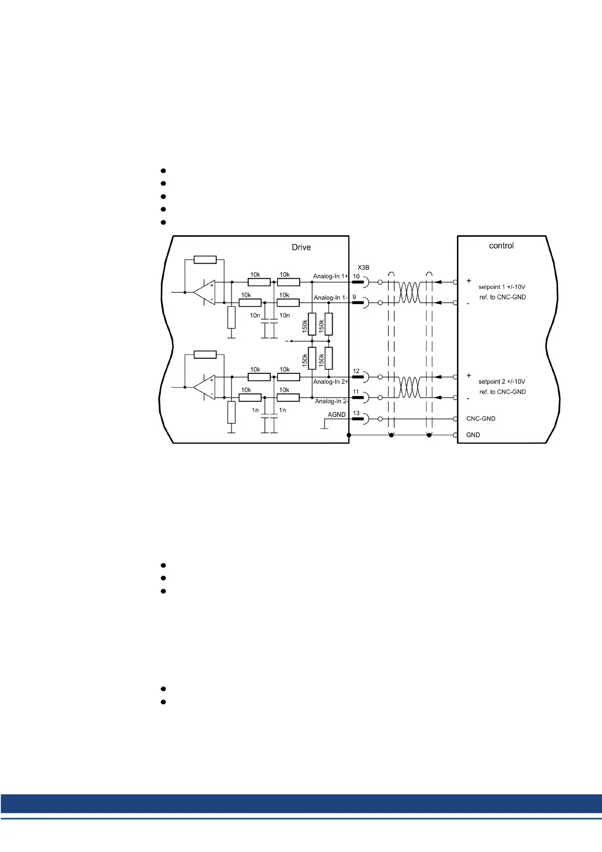
9.15.1 Analog Inputs (X3B)
The servo amplifier is fitted with two programmable differential inputs for analog setpoints.
AGND (X3B/13) must always be joined to control GND as a ground reference.
Technical characteristics
Differential-input voltage max. ± 10 V
Ground reference AGND, terminal X3B/13
Input resistance 150 k
Common-mode voltage range for both inputs ± 10 V
Update rate 62.5 μs
Analog-In 1 input (terminals X3B/10-X3B/9)
Differential input voltage max. ± 10 V, resolution 16 Bit (accuracy 13 Bit), scalable.
Standard setting: speed setpoint
Analog-In 2 input (terminals X3B/12-X3B/11)
Differential input voltage max. ± 10 V, resolution 16 Bit (accuracy 13 Bit), scalable.
Standard setting: torque setpoint
Application examples for setpoint input Analog-In 2:
adjustable external current limit
reduced-sensitivity input for setup or jog operation
pre-control, override
If an input was freshly assigned to a pre-programmed function, then the data set must be
saved in the EEPROM of the servo amplifier and a reset has to be carried out (with the amp-
lifier setup software for example).
Defining the direction of rotation
Standard setting : clockwise rotation of the motor shaft (looking at the shaft end)
Positive voltage between terminal X3B/10 (+ ) and terminal X3B/9 (- ) or
Positive voltage between terminal X3B/12 (+ ) and terminal X3B/11 (- )
To reverse the direction of rotation, swap the connections to terminals X3B/10-X3B/9 or
X3B/12-X3B/11 respectively, or change the COUNT DIRECTION parameter in the “Feed-
back” screen page.
S748-772 Instructions Manual | 9 Electrical Installation
Kollmorgen | kdn.kollmorgen.com | July 2019 99
 Loading...


