2. It
also makes up the intake air path (intake port)
and exhaust gases path (exhaust port).
Using
a helical structure on the intake integrates
more air and mixes fuel with the air.
Use of two valves on the exhaust side quickly
expels the exhaust gases.
3. A passageway for cooling water (water jacket) is
provided to suppress rise in temperature of the
engine.
4. A passageway to allow oil to flow used for the valve
train is provided in the upper part of the cylinder
head.
2.5 Cylinder head cover
2.5.1 Outline of cylinder head cover
The cylinder head cover is a part that covers the valve
train.
The cylinder
head cover prevents scattering of
lubricating oil from the valve train and suppresses noise
emissions.
2.5.2 Structure of cylinder head cover
The cylinder head cover is mounted to the cylinder
head.
(1) Cylinder head cover
2.5.3 Function of cylinder head cover
The primary function of the cylinder head cover is to
prevent scattering of lubricating oil from the valve train.
Further
,
another function is to suppress noise
emissions.
Furthermore, the interior side of the cylinder head cover
is provided with a structure in the passage blow-by gas
flows in for liquifying oil enabling the oil to stay within
the head cover.
The half float type cylinder head cover reduces noise
from the cylinder head.
2.6 Breather
2.6.1 Outline of breather
The breather is a component that releases blow-by
gases generated during the combustion stroke.
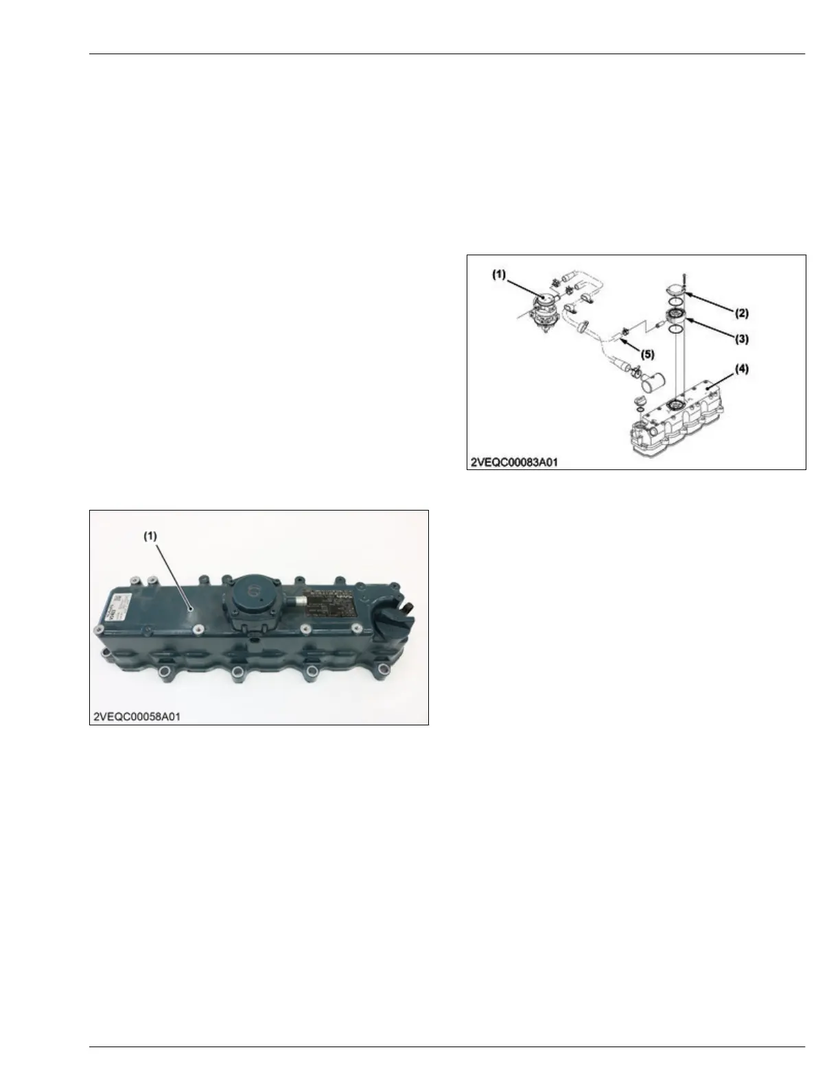
2.6.2 Structure of breather
The breather is made up of a breather valve,
diaphragm, and breather pipe.
(1) Oil separator
(2) Breather valve
(3)
Diaphragm
(4) Cylinder head cover
(5) Breather hose
2.6.3 Function of breather
The breather releases blow-by gases generated during
the combustion stroke.
The breather
is provided with a diaphragm type valve
and mitigates pressure changes in the crankcase.
2.7 Oil separator
2.7.1 Outline of oil separator
The oil separator separates oil and gases in the blow-
by gases.
Separated oil is returned to the oil pan.
The gas
is fed to the intake side hose and re-
combusted.
MECHANISM
2. Engine body 4. ENGINE
D1803-CR-E4,D1803-CR-TE4,D1803-CR-TIE4,V2403-CR-E4,V2403-CR-TE4,V2403-CR-TE4BG,V2403-CR-TIE4

 Loading...


