4. Apply
Prussian Blue to the contact surface to
measure the seated rate.
NOTE
• If the
seated rate is less than 70%, lap the
valve again.
IMPORTANT
• After you complete the valve lapping and
assemble the valve, check the valve
recessing and adjust the valve clearance.
(1) Good
(2) Bad
(3)
Bad
RELATED PAGE
7.4 Checking valve recessing on page 4-164
4.2 Adjusting valve clearance on page 4-98
7.6 Checking clearance between
valve stem and valve guide
Tools required
• External micrometer
• Small hole gauge
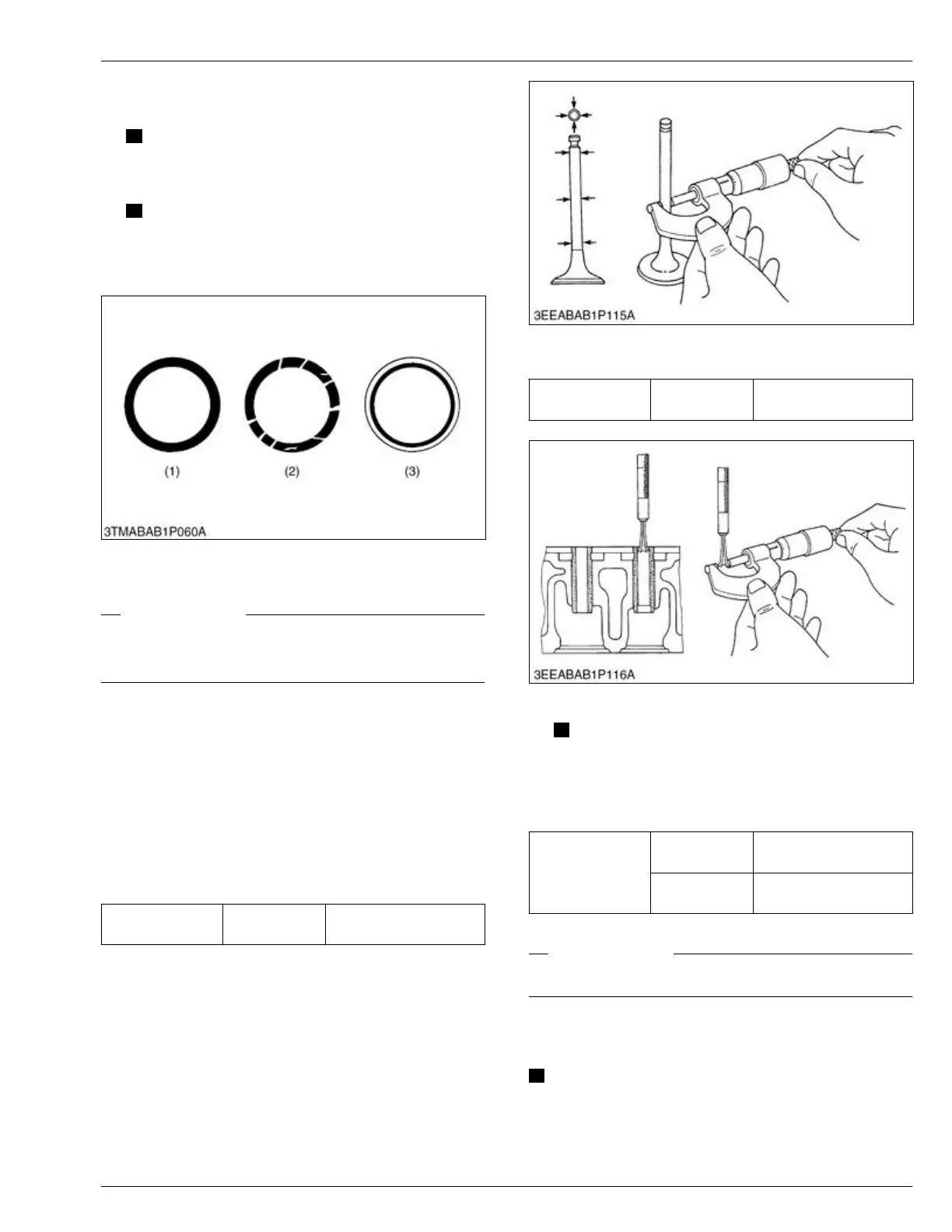
1. Remove carbon from the valve guide section.
2. Measure the valve stem O.D. with an external
micrometer.
Valve stem O.D.
Service specifi-
cation
7.960 to 7.975 mm
0.3134 to 0.3139 in.
3. Measure the
valve guide I.D. with a small hole
gauge.
Valve guide I.D.
Service specifi-
cation
8.015 to 8.030 mm
0.3156 to 0.3161 in.
4. Calculate the clearance.
NOTE
• If
the
clearance is more than the service
limit, replace the valves.
• If the clearance stays more than the service
limit, replace the valve guide also.
Clearance be-
tween valve stem
and valve guide
Service specifi-
cation
0.040 to 0.070 mm
0.0016 to 0.0027 in.
Service limit
0.10 mm
0.0039 in.
RELATED PAGE
7.7 Replacing valve guide on page 4-165
7.7 Replacing valve guide
IMPORTANT
• Do not
hit the valve guide with a hammer during
replacement.
SERVICING
7. Servicing 4. ENGINE
D1803-CR-E4,D1803-CR-TE4,D1803-CR-TIE4,V2403-CR-E4,V2403-CR-TE4,V2403-CR-TE4BG,V2403-CR-TIE4