3. Calculate the air gap (A) from 2 values.
Air gap (A)
Service specifi-
cation
0.30 to 1.5 mm
0.012 to 0.059 in.
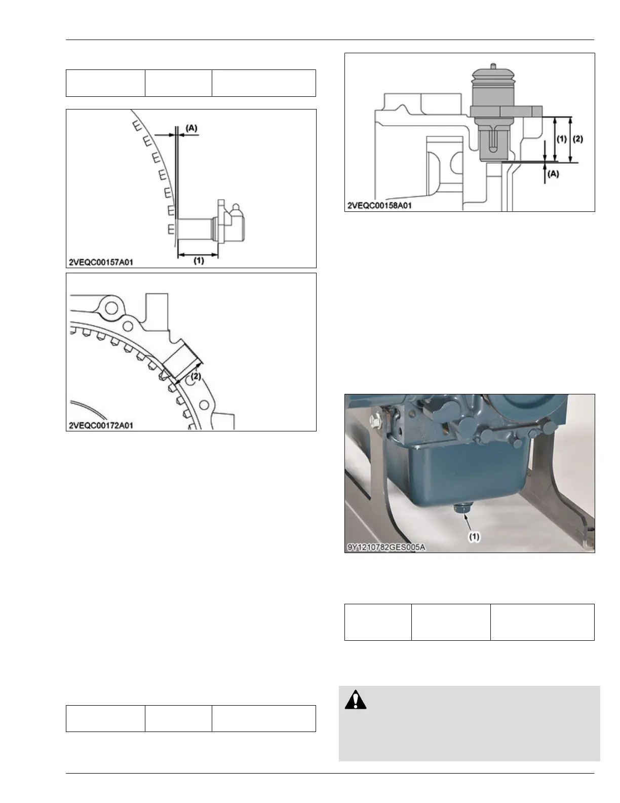
(1) Crankshaft position sensor
length between the sensor
tip and sensor flange
(2) Depth from sensor attaching
face of flywheel housing to
flywheel side
(A)
Air gap
4.32 Adjusting air gap between
camshaft position sensor and pulsar
gear
Tools required
• V
ernier caliper
• Depth gauge
1. Measure the camshaft position sensor length
between the sensor tip and sensor flange face (1)
with vernier caliper.
2. Measure the depth from sensor attaching face of
gear case cover to pulsar gear side surface (2) with
depth gauge.
3. Calculate the air gap (A) from 2 values.
Air gap (A)
Service specifi-
cation
0.20 to 1.3 mm
0.0079 to 0.051 in.
(1) Camshaft position sensor
length between the sensor
tip and sensor flange face
(2) Depth from sensor attaching
face of gear case cover to
pulsar gear side surface
(A)
Air gap
5. Disassembling
5.1 Draining engine oil
1. Start and increase the temperature of the engine for
approximately 5 minutes.
2.
Put an oil pan below the engine.
3. Remove the drain plug (1) to drain the engine oil.
(1) Drain plug
4. After you drain, tighten the drain plug (1) to the
specified torque.
Tightening tor-
que
Drain plug (1)
32.4 to 37.2 N⋅m
3.31 to 3.79 kgf⋅m
23.9 to 27.4 lbf⋅ft
5.2 Draining coolant
CAUTION
• Do not
remove the radiator cap while you
operate or immediately after you stop the
engine.
• If not, hot water can flow out from the radiator.
SERVICING
4. Checking and adjusting 4. ENGINE
D1803-CR-E4,D1803-CR-TE4,D1803-CR-TIE4,V2403-CR-E4,V2403-CR-TE4,V2403-CR-TE4BG,V2403-CR-TIE4

 Loading...


