4. Intake and exhaust system
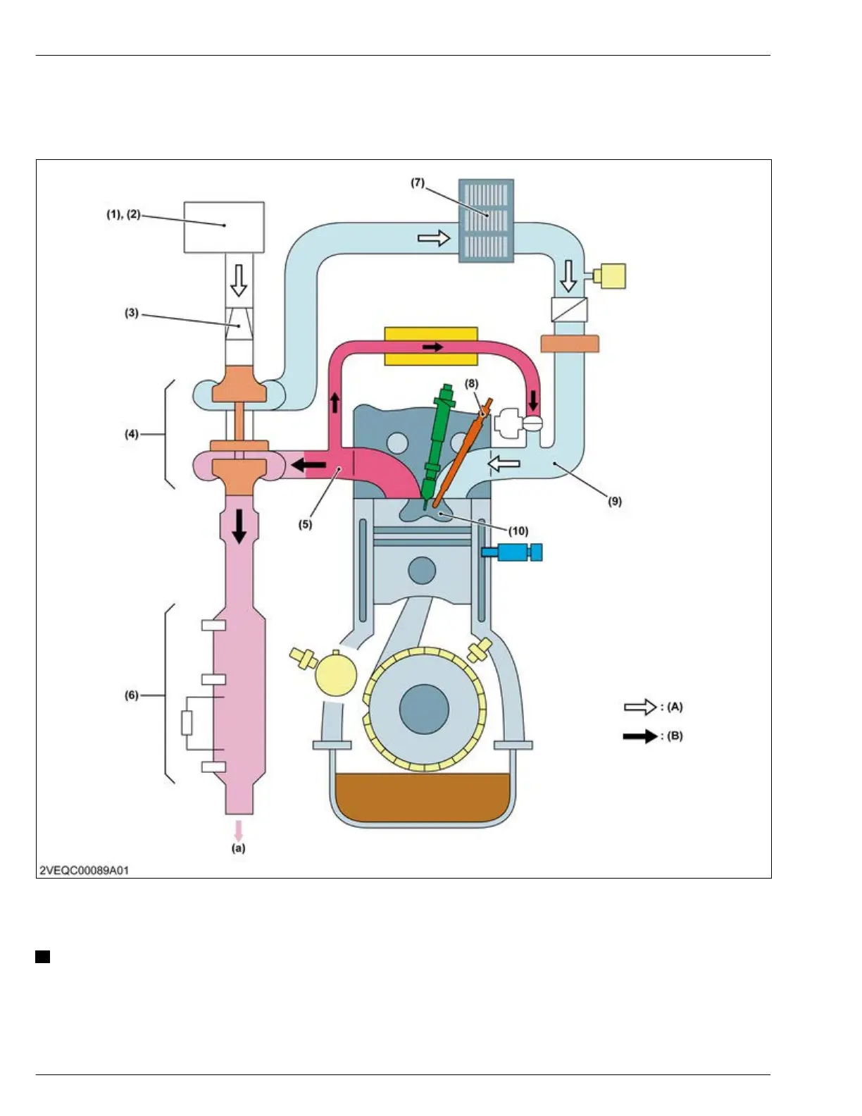
4.1 Structure of intake and exhaust system
The intake and exhaust system is made up of intake system and exhaust system components.
(1) Pre-cleaner
(2) Air cleaner
(3)
Air flow sensor
(4) Turbocharger
(5) Exhaust manifold
(6) *Aftertreatment unit (DPF)
(7) **Intercooler
(8) Glow plug
(9) Intake manifold
(10) Combustion chamber
(A) Intake air flow
(B) Exhaust gas flow
(a) Exhaust gas
NOTE
• The parts marked with * is called aftertreatment unit (DOC) for D1803-CR-TIE4 and V2403-CR-TIE4.
•
The parts marked with ** are equipped only for D1803-CR-TIE4 and V2403-CR-TIE4.
4. ENGINE
MECHANISM
4. Intake and exhaust system
D1803-CR-E4,D1803-CR-TE4,D1803-CR-TIE4,V2403-CR-E4,V2403-CR-TE4,V2403-CR-TE4BG,V2403-CR-TIE4