NOTE
• Do not
use an impact wrench. Serious damage
will occur.
Tools required
• Flywheel stopper
• Flywheel guide screw
1. Set the flywheel guide screw (2).
2. Install the flywheel (1).
3. Attach the flywheel stopper and tighten to the
specified torque.
NOTE
• Apply engine oil to the flywheel screws.
• Check that there are no metal particles that
remain on the flywheel mounting surfaces.
• The flywheel and the crankshaft fit together
in just one position. Make sure they are
securely fit and tighten the screws.
Tightening tor-
que
Flywheel screw
98.10 to 107.9 N⋅m
10.01 to 11.00 kgf⋅
m
72.36 to 79.58 lbf⋅ft
(1) Flywheel (2) Flywheel guide screw
RELATED PAGE
4.30 Measuring angular deviation between crankshaft
T.D.C. and crankshaft position sensor detected T.D.C.
on page 4-112
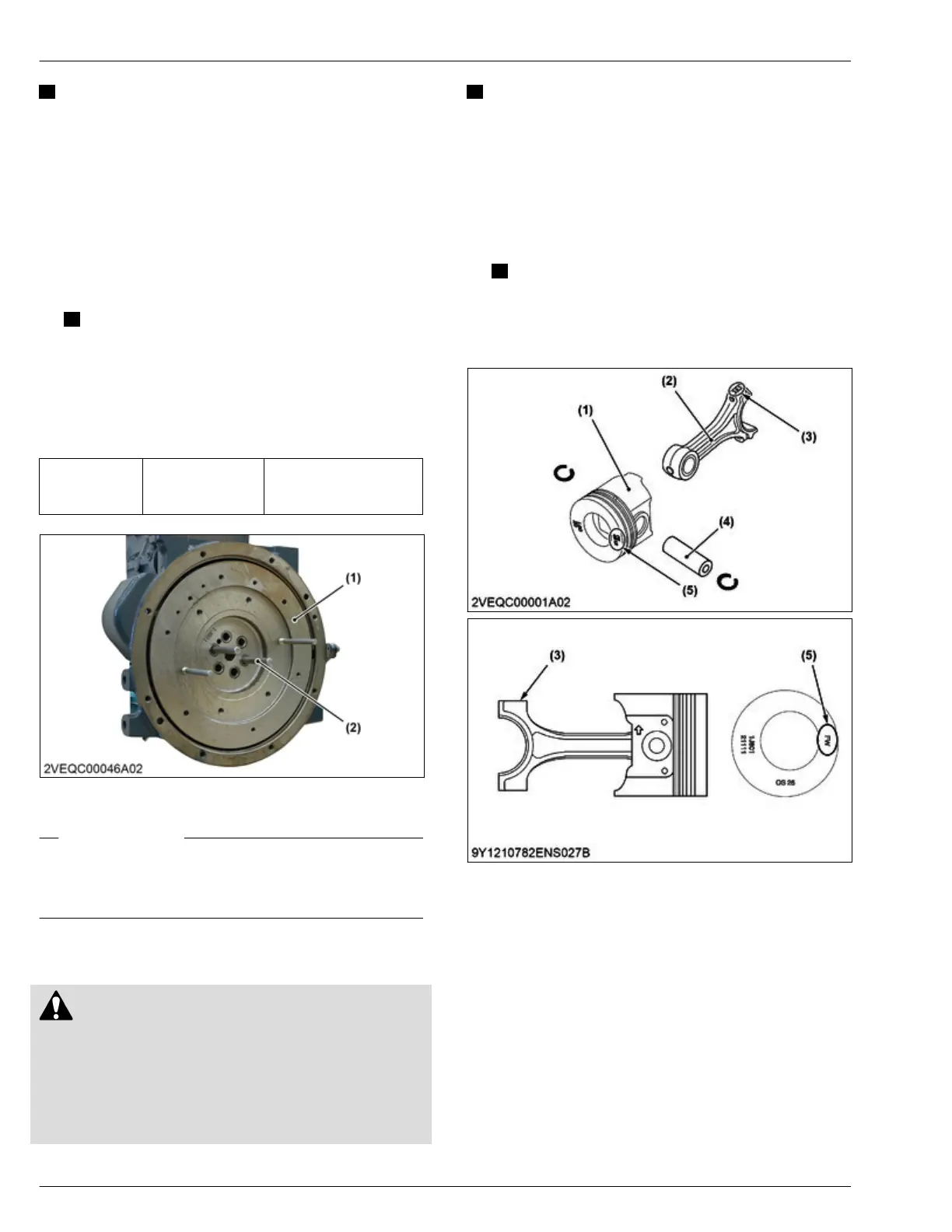
6.9 Assembling piston assembly
CAUTION
• The end
faces of the oil ring are plated with
hard chrome. When you install the piston into
the cylinder, do not give a damage to the
cylinder by the oil ring. If the ring's planting is
scratched, it may get stuck on the cylinder wall,
causing serious damage.
IMPORTANT
• Put a
mark on the connecting rod and the
piston with the same number to keep the same
combination.
1. Put the piston fully in 80 ℃ (176 ℉) oil for 10 to 15
minutes.
2. Install the piston pin (4) and the connecting rod (2)
to the piston (1).
NOTE
• Apply engine oil to the piston pin.
• Align the mark [FW] (5) on the piston to the
flywheel side and the connecting rod mark
(3) to the supply pump side.
(1) Piston
(2) Connecting rod
(3)
Mark
(4) Piston pin
(5) Mark [FW]
4. ENGINE
SERVICING
6. Assembling
D1803-CR-E4,D1803-CR-TE4,D1803-CR-TIE4,V2403-CR-E4,V2403-CR-TE4,V2403-CR-TE4BG,V2403-CR-TIE4