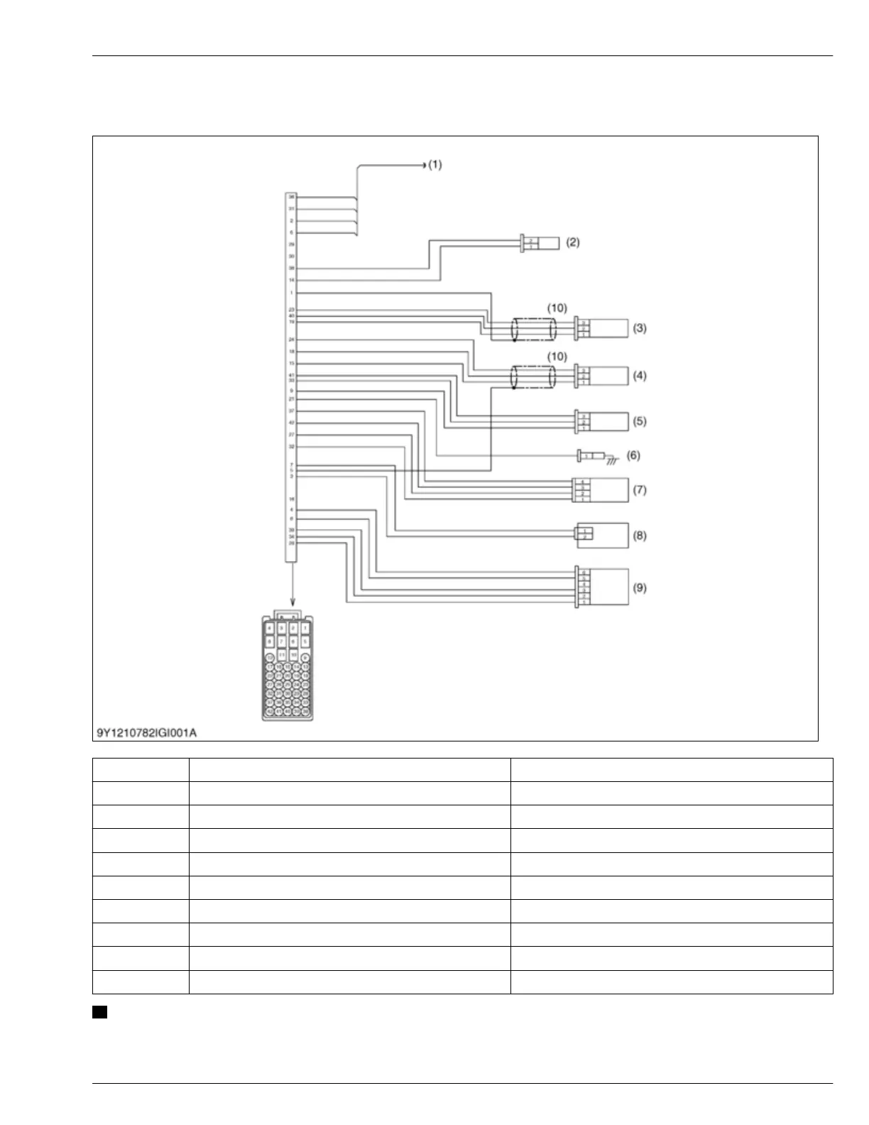
6. Wiring diagram
6.1 Engine intermediate harness (Engine side harness)
(1) - CAN and EGR
(2) CN202 Coolant temperature sensor
(3) CN204 Crankshaft position sensor
(4) CN205 Camshaft position sensor
(5) CN206 Rail pressure sensor
(6) CN207 Oil pressure switch
(7) CN208 Boost pressure sensor
(8) CN209 Suction control valve (SCV)
(9) CN210 Intake throttle valve
(10) - Shield cable
NOTE
• The figure shows the pin arrangement of the connector housing viewed from wire side, not mating side.
GENERAL MACHINE INFORMA
TION
6. Wiring diagram 2. GENERAL
D1803-CR-E4,D1803-CR-TE4,D1803-CR-TIE4,V2403-CR-E4,V2403-CR-TE4,V2403-CR-TE4BG,V2403-CR-TIE4