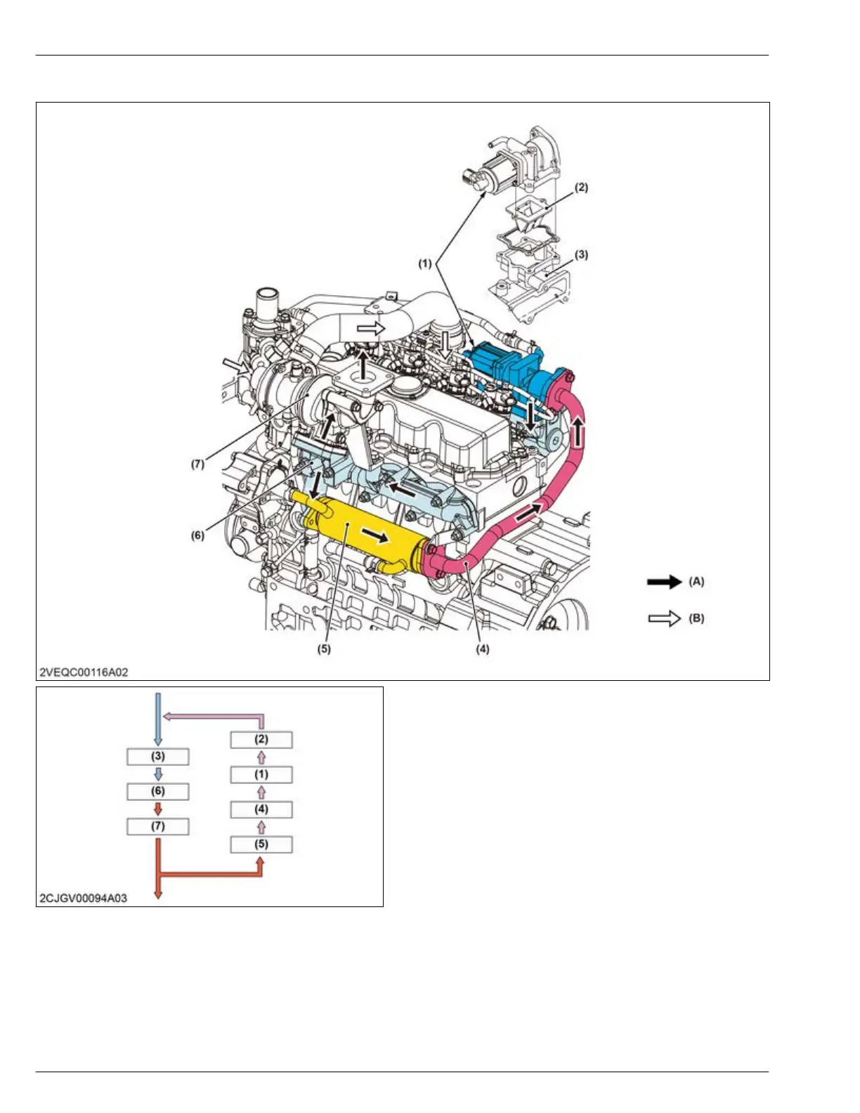
5.3 Flow of EGR system
(1) EGR valve
(2) Reed valve
(3)
Intake manifold
(4) EGR pipe
(5) EGR cooler
(6) Exhaust manifold
(7) Turbocharger
(A) Exhaust gas flow
(B) Intake air flow
1. A part of the exhaust gases that pass through the turbocharger (7) are cooled in the EGR cooler (5).
2. Thereafter the
gases pass through the EGR pipe (4), EGR valve (1), reed valve (2), and are returned to the intake
manifold (3).
3. Intake air and exhaust gases are mixed in the intake manifold (3) and are fed to the combustion chamber.
4. ENGINE
MECHANISM
5. Exhaust gas recirculation (EGR) system
D1803-CR-E4,D1803-CR-TE4,D1803-CR-TIE4,V2403-CR-E4,V2403-CR-TE4,V2403-CR-TE4BG,V2403-CR-TIE4