(26) CN407 CAN connector cap
(27) - Shield cable
NOTE
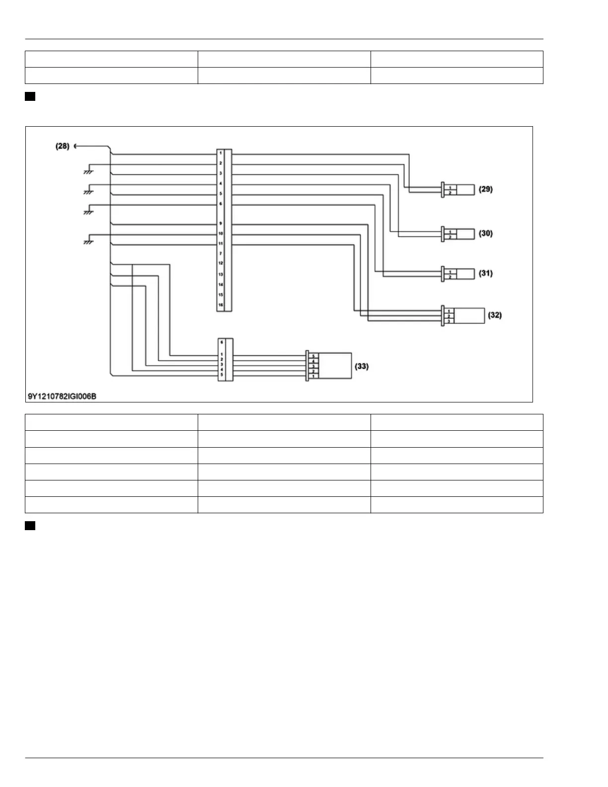
• The figure shows the pin arrangement of the connector housing viewed from wire side, not mating side.
(28) - Diesel particulate filter (DPF)
(29) CN101 Exhaust gas temperature sensor (T2)
(30) CN102 Exhaust gas temperature sensor (T1)
(31) CN103 Exhaust gas temperature sensor (T0)
(32) CN104 Differential pressure sensor (ΔP)
(33) CN105 Air flow sensor
NOTE
• The figure shows the pin arrangement of the connector housing viewed from wire side, not mating side.
2. GENERAL
GENERAL MACHINE INFORMA
TION
6. Wiring diagram
D1803-CR-E4,D1803-CR-TE4,D1803-CR-TIE4,V2403-CR-E4,V2403-CR-TE4,V2403-CR-TE4BG,V2403-CR-TIE4