7 Installation, connection, exchange (continued)
87 of 206
BA KR 6, 16 F, KR C4 12.10.07 en
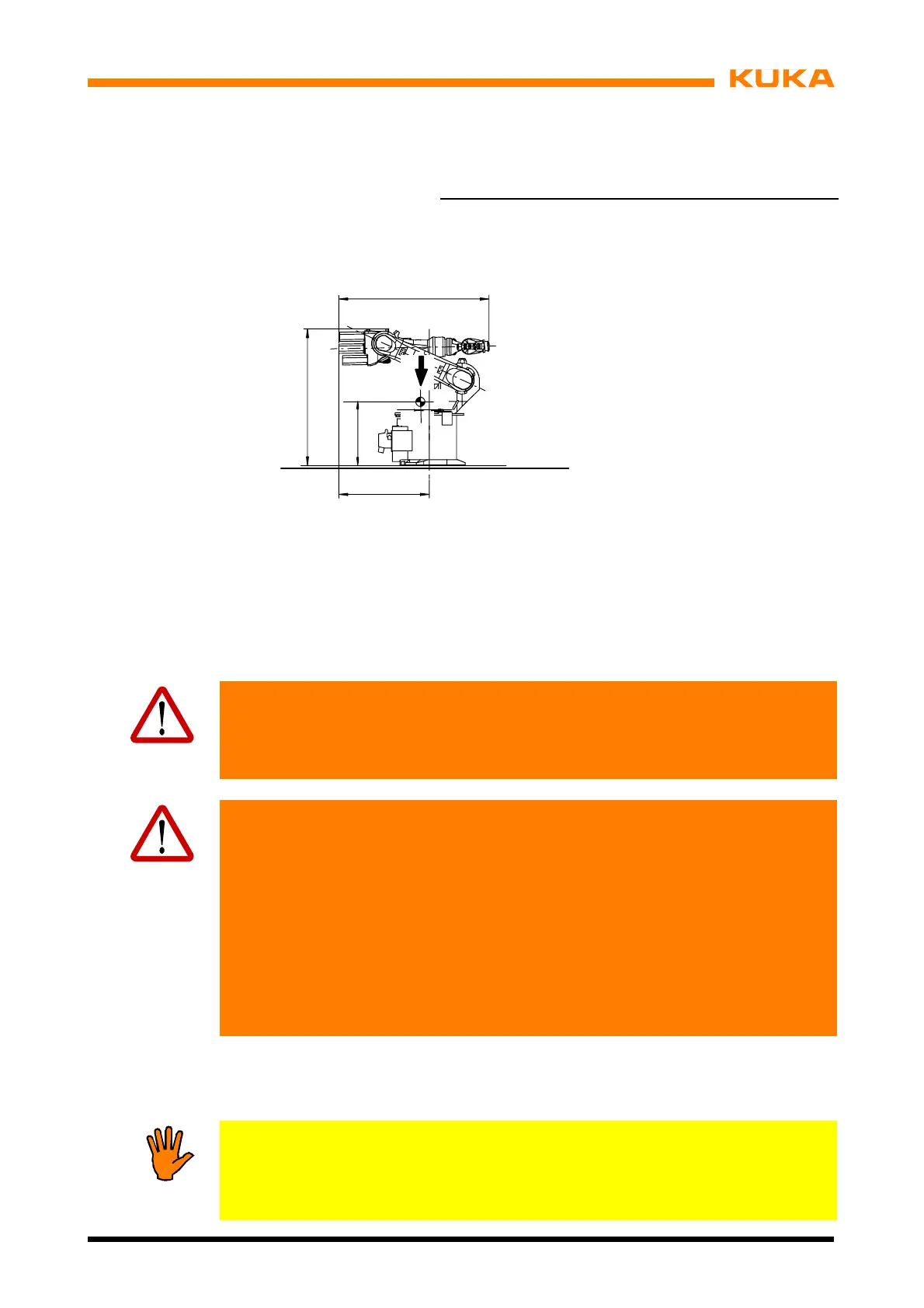
A1 A2 A3 A4 A5 A6
0˚
---155˚ +154˚ 0˚ 0˚ 0˚*
ll angles are speci
ied relative to the electrical “zero position”
or to the KCP display.
1078
G = 235 kg KR 6, KR 16,
240 kg KR 16 L6
552
G
19
1115
1)
1184
2)
1416
3)
686
1)
711
2)
686
3)
1)
KR 6
2)
KR 16
3)
KR 16 L6
Fig. 60 Transport position for floor --mounted manipulators
(2) Raise the manipulator with a fork lift truck or lifting tackle attached to three eyebolts on
the rotating column.
Caution!
For reasons of safety, it is imperative for the lifting tackle to be attached to the
manipulator at the specified points.
Risk of injury! The transport instructions in Chapter 6 must be observed.
Caution!
If the manipulator is transported by fork lift truck, the forks must be placed in the
slots in the base frame. It is forbidden to pick up the manipulator in any other
wayusingaforklifttruck!
The manipulator must remain in its transport position until it is -- depending on
the type -- fastened to the floor, the ceiling or to a hinged steel base.
Before the manipulator is lifted, it must be ensured that it is free from
obstructions. Transport safeguards, such as nails and screws, are all to be to be
removed in advance, as is any rust or glue on contact surfaces.
Excessive loading of the fork slots through undue inward or outward movement
of hydraulically adjustable forks of the fork lift truck is to be avoided.
(3) Lower the manipulator (Fig. 61/5) vertically onto bedplates (4) or steel structure. If lifting
tackle is used, particular care must be taken to ensure exact vertical positioning in order
to avoid damaging the pins during this operation.
Notice!
As the manipulator is lowered, the boreholes (2) must be aligned as accurately
as possible with the two pins (3). If this operation is carried out inaccurately, it is
more likely that parts will be damaged.
 Loading...


