Operating Instructions
90 of 206
BA KR 6, 16 F, KR C4 12.10.07 en
A1 A2 A3 A4 A5 A6
0˚
---155˚ +154˚ 0˚ 0˚ 0˚ *
* All angles are specified relative to the electrical “zero position”
or to the KCP display.
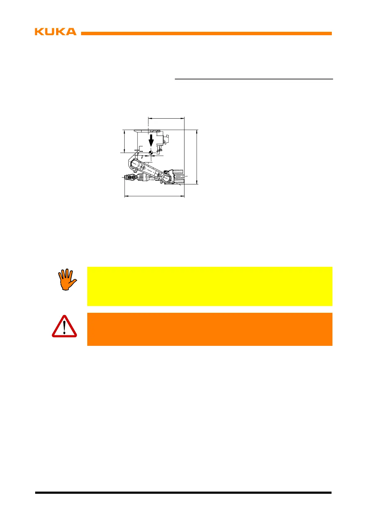
1115
1)
1184
2)
1416
3)
G = 235 kg KR 6, KR 16
240 kg KR 16 L6
552
G
19
1)
KR 6
2)
KR 16
3)
KR 16 L6
686
1)
711
2)
686
3)
1075
Fig. 63 Transport position for ceiling--mounted manipulators
(2) Raise the manipulator (Fig. 64/4) vertically with the fork lift truck and place it onto the
ceiling structure (1).
Notice!
As the manipulator is raised, the boreholes (3) must be aligned as accurately as
possible with the two pins (2). If this operation is carried out inaccurately, it is
more likely that parts will be damaged.
Caution!
As soon as the manipulator is in its exact position on the ceiling, it must be
pressed firmly against the ceiling until it is finally bolted to it.
(3) Insert M20x55 ISO 4017 hexagon bolts (5) together with conical spring washers and
tighten them with a torque wrench in diagonally opposite sequence, increasing the tight-
ening torque M
A
to the specified value in several stages (M
A
= 370 Nm).
 Loading...


