EasyManuals Logo

Kyocera Ecosys M6526cdn Service Manual

Kyocera Ecosys M6526cdn
375 pages
To Next Page IconTo Next Page
To Previous Page IconTo Previous Page
Page #267 background imageLoading...
Page #267 background image
2PV/2PW-2
1-5-77
(Align the FFC wire at the main PWB side.)
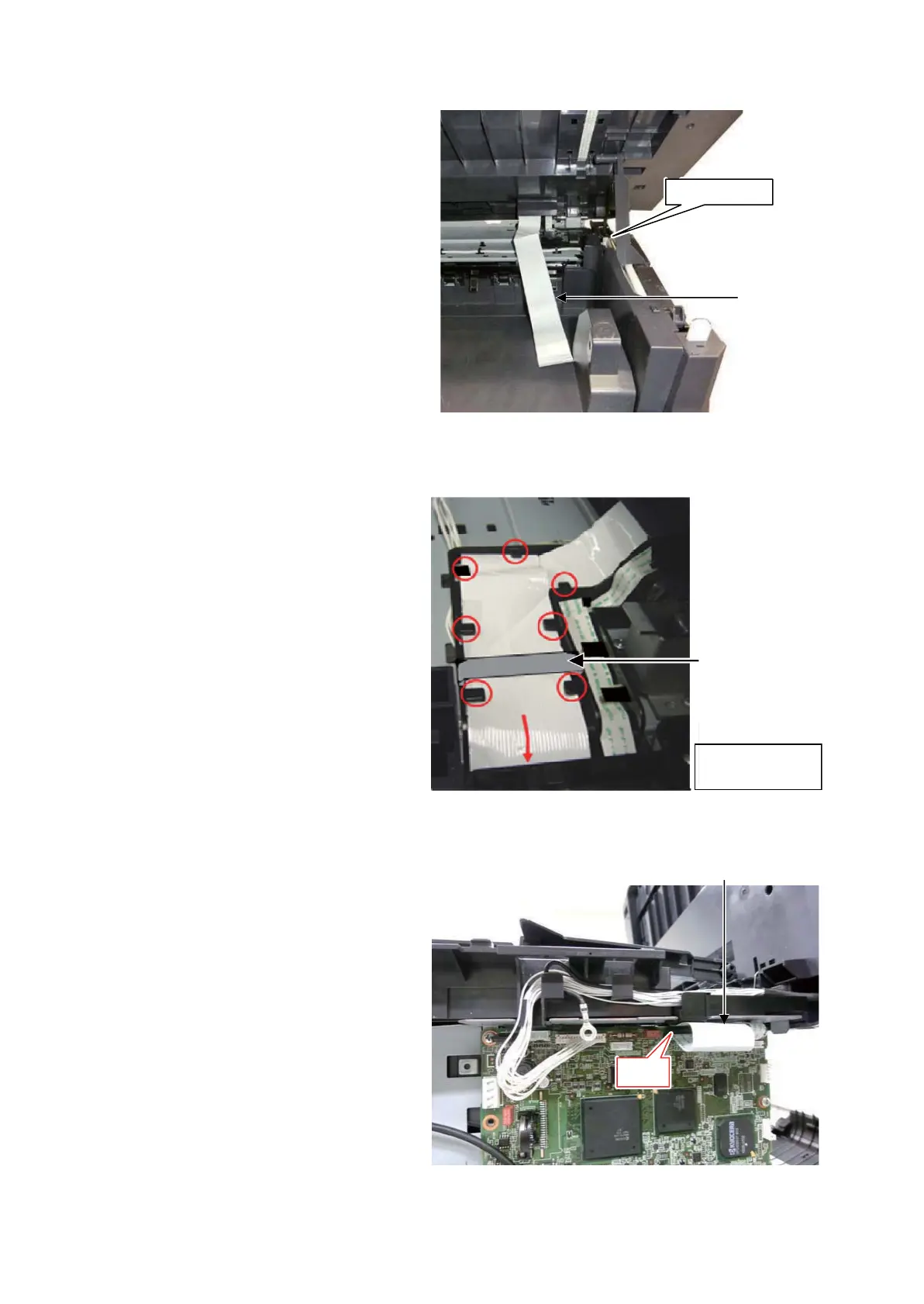
65. Remove the left and right holders of the
scanner unit at Step 20, 21 and fully
open the scanner unit.
Figure 1-5-124
66. Align the FFC wire like the figure to the
right.
(Seven alignment ribs and one ferrite
core)
Figure 1-5-125
67. Insert the end of the FFC wire into the
connector YC8 on the main PWB.
68. Refit all the parts and the unit detached
in the reverse manner of the above pro-
cedures.
Figure 1-5-126
FFC wire
Wire holder
Alignment ribs
are circled in red.
Ferrite core
(Wire holder viewed from the machine right side)
YC8
FFC wire

Table of Contents

Other manuals for Kyocera Ecosys M6526cdn

Questions and Answers:

Question and Answer IconNeed help?

Do you have a question about the Kyocera Ecosys M6526cdn and is the answer not in the manual?

Kyocera Ecosys M6526cdn Specifications

General IconGeneral
BrandKyocera
ModelEcosys M6526cdn
CategoryAll in One Printer
LanguageEnglish

Related product manuals