User Guide
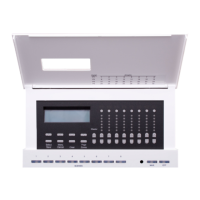
Leviton D4200 LCD Ver 2.0 Architectural Lighting Controller Page 28 of 80
Assigning Zones (Patching Zones to
Dimmer Channels) - MANDATORY
The dimmer circuit channel number is assigned/patched to Luma-Net
channels in the dimmer cabinet. A Zone can consist of a single
dimmer, or several dimmers all driving a common area. For example,
in a large church each chandelier might need one whole dimmer for
power, but all chandeliers would be one Zone so the lights would all
go up and down together. In the case of six chandeliers you would
need six dimmers. The Zone assignment must be set to match the
corresponding Luma-Net channel numbers in dimmer cabinets or
control equipment.
Default Settings
The factory default setting assigns Zone 1 to drive Luma-Net channel
1, Zone 2 to drive Dimmer 2, Zone 3 to drive Dimmer 3, etc. However,
if input Zone 01 drives output dimmers 01, 02, and 03, input Zone 02
would need to be assigned to output dimmer 04.
The default setting is generally satisfactory for most simple
installations with one or two D4200 controls and one dimmer cabinet.
Setting START CHANN to a number causes all zones to be assigned
to sequential channel numbers starting with that same number and
adding one to each zone there after. Setting START CHANN to NONE
causes all zones to be assigned NONE. This is useful when only a few
zones are to be used.
Unused zones should be set to NONE to disable LED level
display for that zone. Also see the “Exclude Menu” in the
operator’s manual.
Using the Patching table in Appendix A, assign a dimmer circuit
channel number to each of the zones by:
Step 1: Press the Menu/Cancel button.
Step 2: Press the Up or Down buttons until ASSIGN
ZONES? flashes on the display.
Step 3: Press the Select/Save button.
Step 4: Press the Up or Down buttons to scan through
the 8, 16, 24 or 32 ZONES and START CHANN.