Using the Long-Term Chambers
7-5
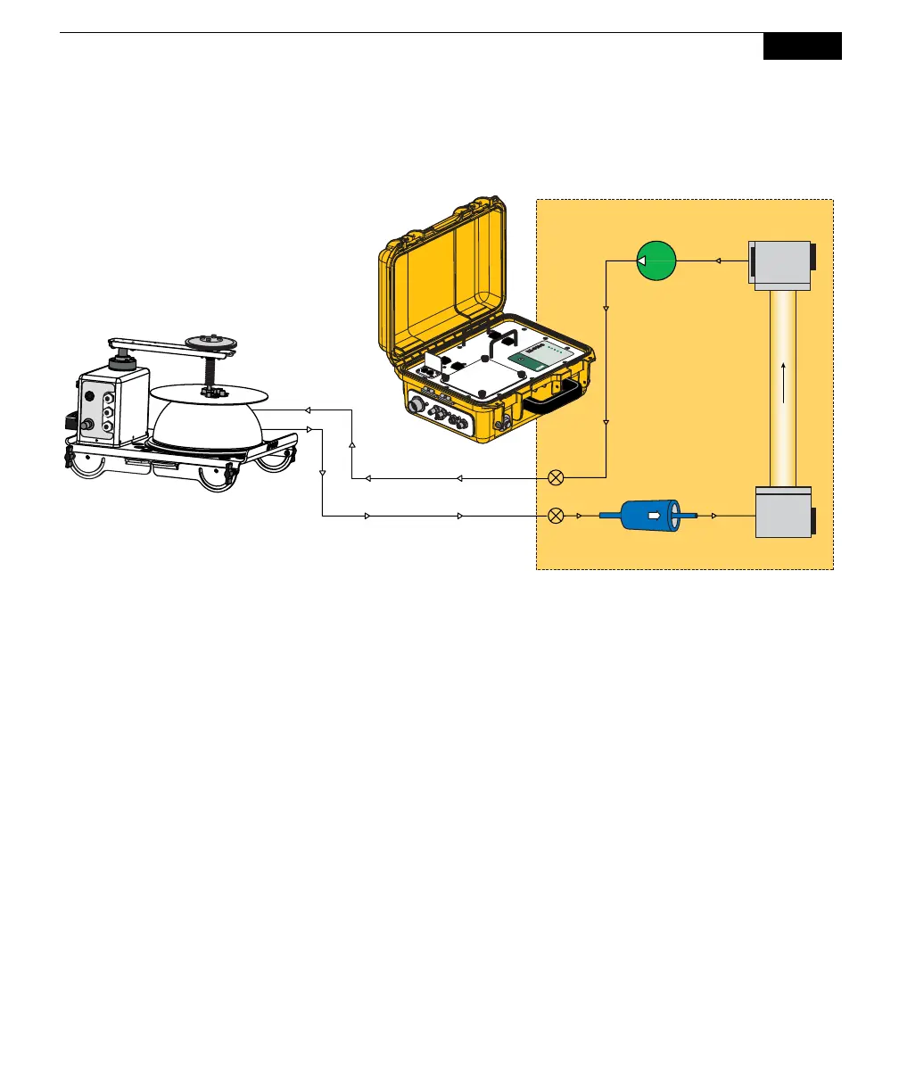
analyzer optical bench measures CO
2
and H
2
O concentrations simultaneously;
these concentrations are then used to calculate flux rate.
ON/OFF
Automated Soil
CO
2
Flux System
ON/OFF
P
O
W
E
R
IR
G
A
R
E
A
D
Y
A
C
T
IV
E
L
O
W
B
A
T
T
E
R
Y
R
E
A
D
Y
ON/OFF
ON/OFF
Diaphragm
Pump
To Chamber
From Chamber
Filter
Analyzer
Bench
Analyzer Control Unit
8100-104/C Chamber
Figure 7-5. The measurement flow path to the 8100-104/C Long-Term Chamber.
Connecting the Long-Term Chambers to the Analyzer Control Unit or Multiplexer
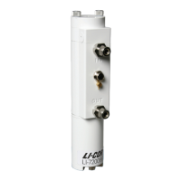
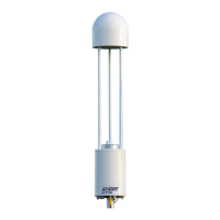
8100-104/C Long-Term Chambers
There are two short hoses connected to the 8100-104/C Long-Term Chambers; air
to the chamber and air returning from the chamber to the Analyzer Control Unit or
LI-8150 Multiplexer. The 8100-104/C requires the use of an additional cable to
connect to the Analyzer Control Unit or the LI-8150 Multiplexer; the 8100-704 is a
2m accessory cable, and the 8150-705 is a 15m accessory cable. These cables are
connected to the side panel of the Analyzer Control Unit, as shown in Figure 2-2,
or the LI-8150 Multiplexer side panel, as shown in Figure 10-8. The Air In hose
has a male fitting, and the Air Out hose has a female fitting. To remove the hoses,
slide the collar on the fittings and pull straight out. A small plug (p/n 9981-118, in
the spares kit) is used to plug the Bellows port. Connect the control cable to the
port labeled CONTROL LINE on the chamber side panel, and to the port labeled
CHAMBER on the Analyzer Control Unit (or CHBR on the LI-8150 Multiplexer).