2-12
Initial Setup
Terminal Label Description
1 V IN + Voltage input positive
2 V IN - Voltage input negative
3 V OUT + 5 VDC output positive
4 V OUT - 5 VDC output negative
5 V OUT + 5 VDC output positive (switched)
6 V OUT - 5 VDC output negative (switched)
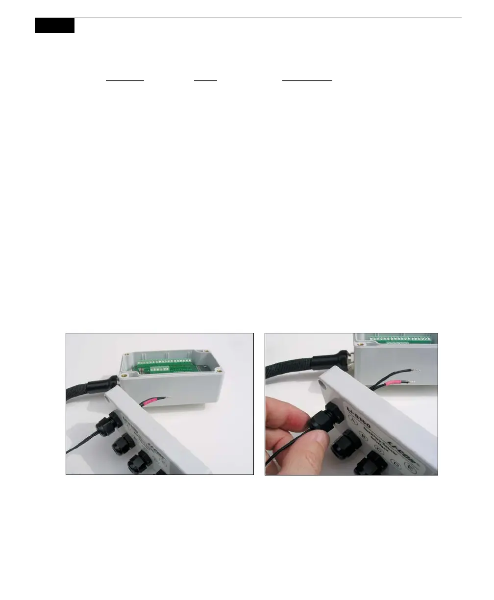
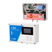
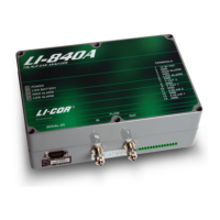
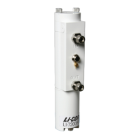
Connecting Sensors to the Auxiliary Sensor Interface
There are 5 compression style strain relief cable glands on the Auxiliary Sensor
Interface top cover, through which the sensor or power supply wires pass, after
which the wires are connected to the appropriate screw terminals. To attach your
sensor(s) or power supply to the Auxiliary Sensor Interface, follow these steps:
1. Remove the philips head screw in each of the 4 corners of the Auxiliary
Sensor Interface module and remove the top cover.
2. Remove the cap from any of the 5 glands by turning counter-clockwise.
3. Pass the wires through the top of the gland cap first, and then through the
gland. Screw the cap slightly, but don’t tighten yet.
4. Use a small flathead screwdriver to loosen the appropriate screw terminal,
and insert the wire leads into the terminal strip. Tighten the screw terminals.
Make a note of which gland the wires are passing through (e.g. A, B, C, D, or
E), and to which terminal the wires are connected (e.g. A/T1, B/V3, etc.). This
information will be needed later when you enter the sensor calibration
coefficients into software.