Initial Setup
2-11
V1
V IN
10.5-28VDC
3A MAX
V OUT
5VDC
30mA
V OUT
5VDC
30mA
SWITCHED
V2 V3 V4 T1 T2 T3 T4
+
GND
+
GND
+
GND
+
GND
GND
GND
+
-
+
-
+
-
+
-
+
-
+
-
+
-
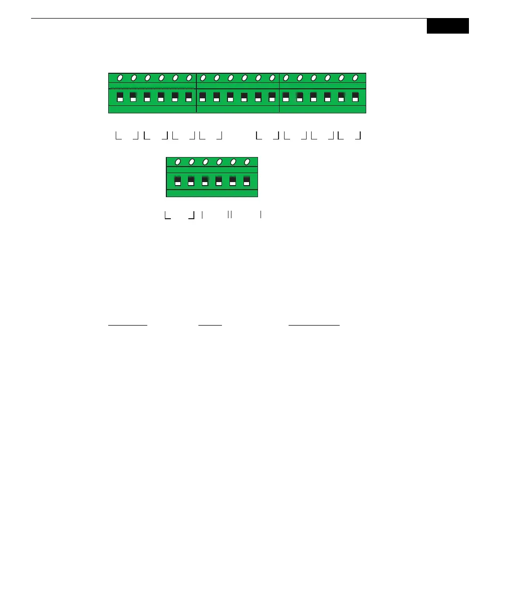
Figure 2-12. Graphical representation of terminal positions.
The terminal positions are numbered and configured as follows, reading left to
right:
Terminal
Label Description
1 V1 + Voltage input 1 positive
2 V1 GND Voltage input 1 ground
3 V2 + Voltage input 2 positive
4 V2 GND Voltage input 2 ground
5 V3 + Voltage input 3 positive
6 V3 GND Voltage input 3 ground
7 V4 + Voltage input 4 positive
8 V4 GND Voltage input 4 ground
9 GND Ground
10 GND Ground
11 T1 + Thermocouple input 1 positive
12 T1 - Thermocouple input 1 negative
13 T2 + Thermocouple input 2 positive
14 T2 - Thermocouple input 2 negative
15 T3 + Thermocouple input 3 positive
16 T3 - Thermocouple input 3 negative
17 T4 + Thermocouple input 4 positive
18 T4 - Thermocouple input 4 negative