2-10
Initial Setup
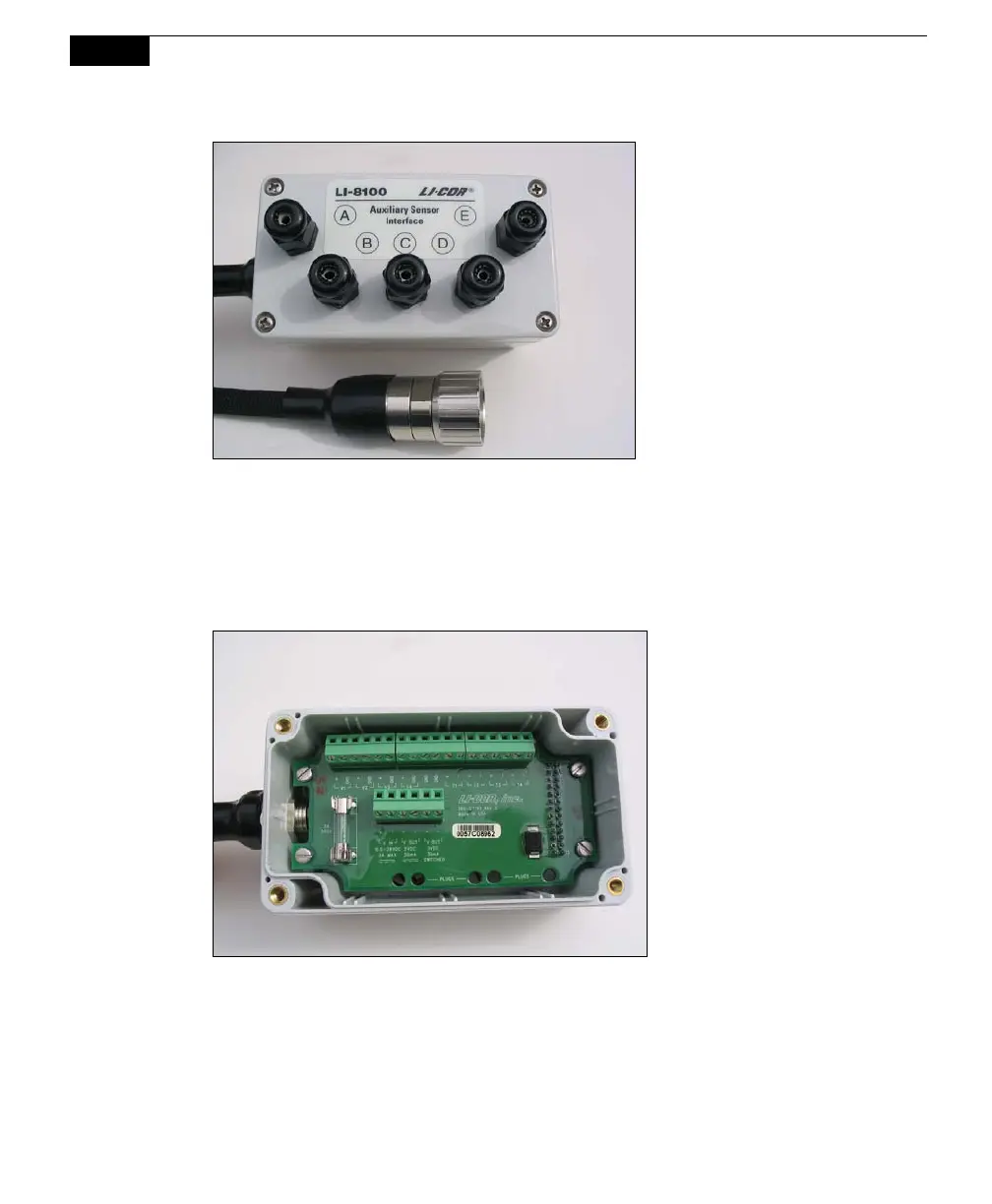
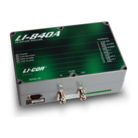
Figure 2-10. Auxiliary Sensor Interface and connector.
Auxiliary Sensor Interface Terminals
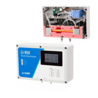
Loosen the 4 philips head screws in each corner of the Auxiliary Sensor Interface
module and remove the top cover. The interior of the interface appears as shown
below.
Figure 2-11. Auxiliary Sensor Interface interior.
Note that there are 2 terminal strips, with connections as follows: