2 Initial Setup
Cable Connections
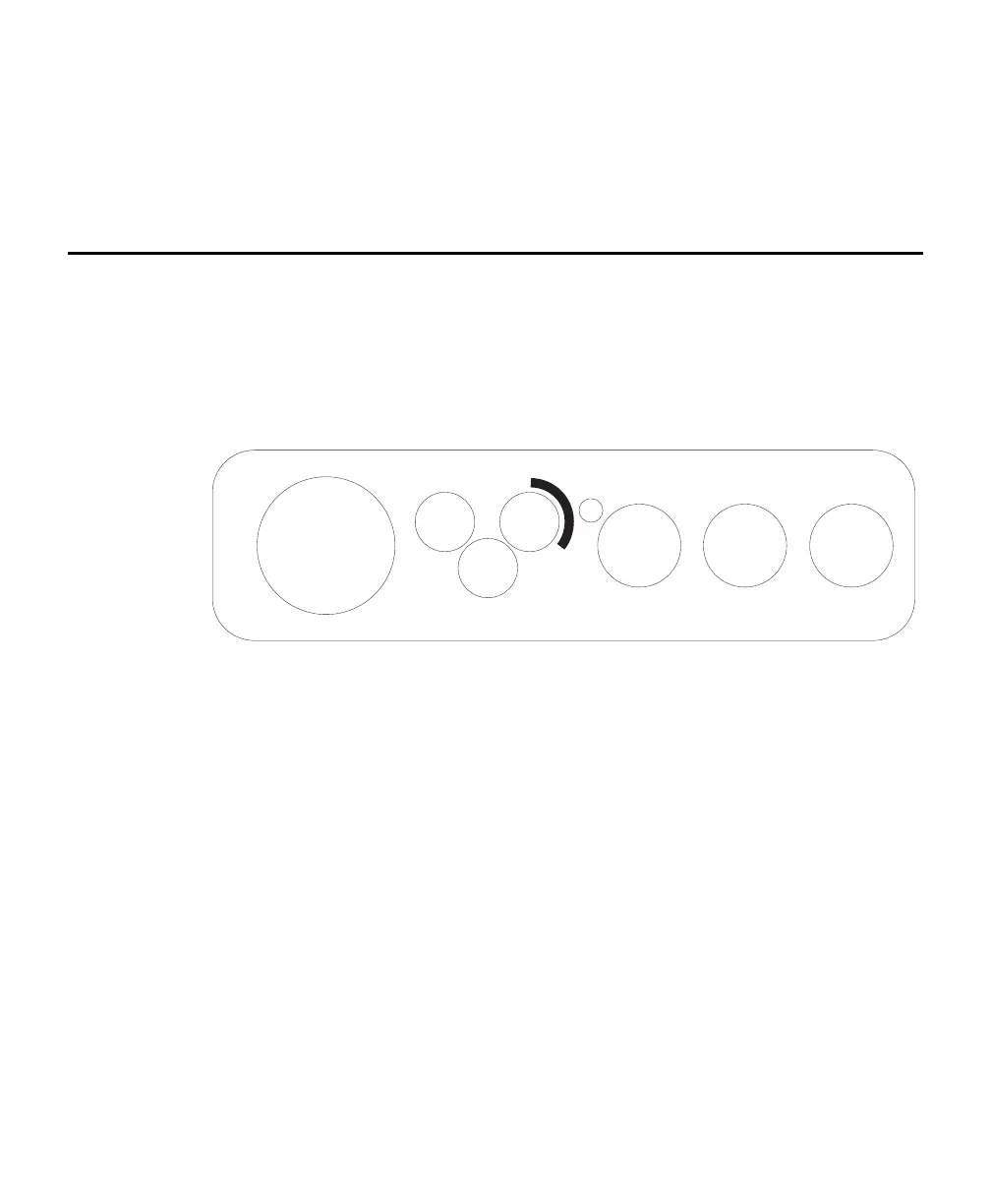
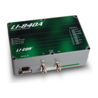
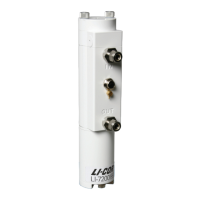
There is a panel for connecting the RS-232, chamber, and Auxiliary Sensor
Interface cables on the left side of the Analyzer Control Unit. The panel appears as
shown in Figure 2-1 below.
AUX. SENSOR
INTERFACE
AIR INAIR OUT
BELLOWS
CHAMBER RS-232
ETHERNET
Figure 2-1. Analyzer Control Unit cable connection panel.
Locate and attach the RS-232 Cable (p/n 392-10587), which is a 1 meter cable with
a round connector on one end that mates to the RS-232 port on the left side of the
Analyzer Control Unit. The other end of the cable has a 9-pin DB-9 connector for
attaching to the serial interface on your computer, or to the 6400-27 RS-232 to
USB adapter, for computers that only have a USB connection.
There are three hoses connected to the Survey Chambers: air to the chamber, air
returning from the chamber to the Analyzer Control Unit, and air that drives the
bellows (Survey Chambers only). The Long-Term Chambers use only two hoses: air
in and air out. These hoses are connected to the side panel of the Analyzer Control
Unit, as shown below. The hose for Air In has a male fitting and the hose for Air
Out has a female fitting. Note that one of the hoses has a piece of black shrink
wrap; this hose attaches to the Air In fitting on the Analyzer Control Unit. The
bellows hose has a male fitting, and attaches to the port marked Bellows on the
Analyzer Control Unit. Insert the hoses until the fittings snap into place. To
remove the hoses, slide the collar on the fittings; the collar on the bellows and Air
In fittings slide toward the Analyzer Control Unit, and the collar on the Air Out
fitting slides away from the Analyzer Control Unit.