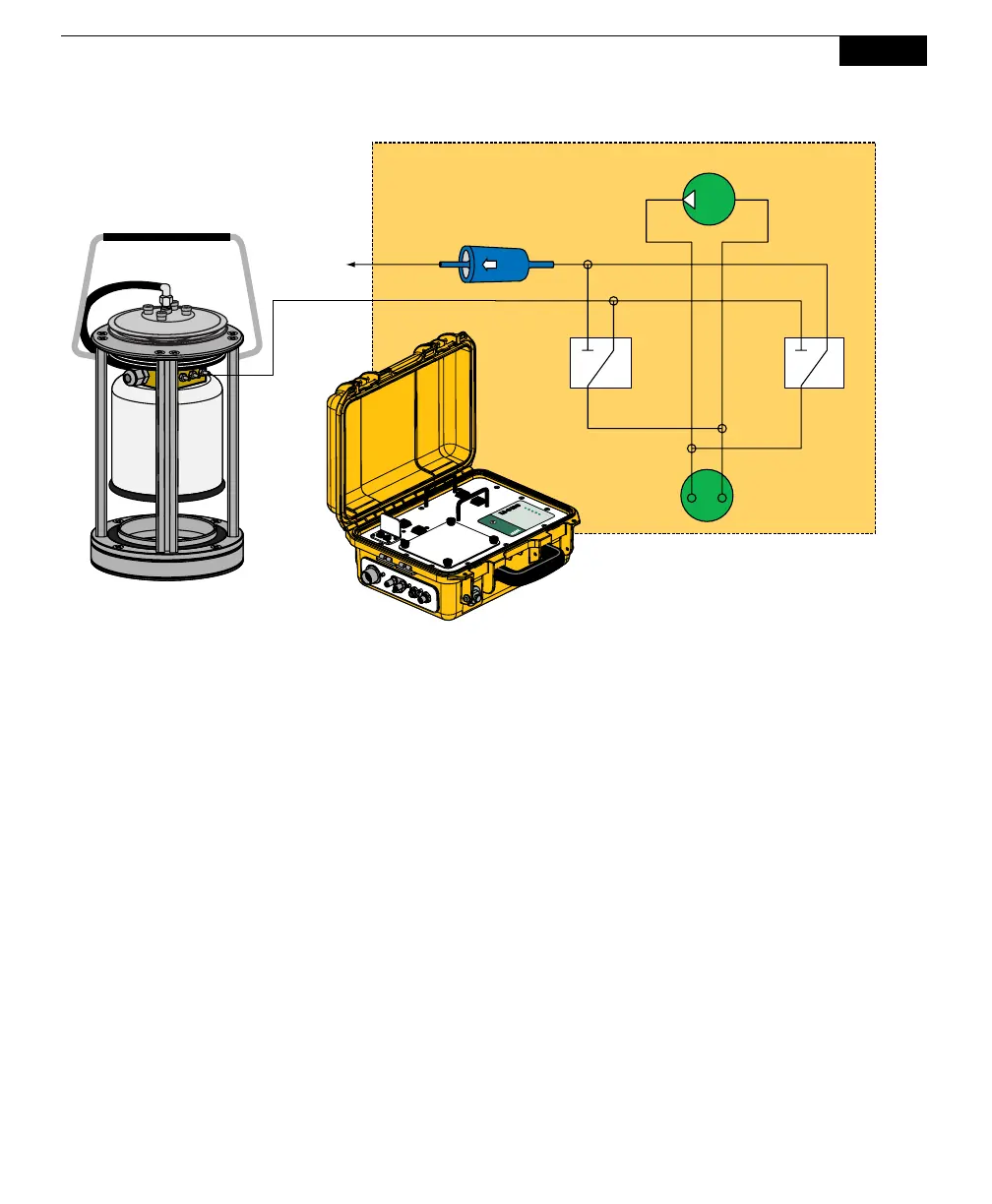
Using the 10 and 20 cm Survey Chambers
6-5
Diaphragm Pump
Pressure
Transducer
Valve
Valve
Filter
Bellows
Vent
Chamber
Analyzer Control Unit
ON/OFF
Automated Soil
CO
2
Flux System
ON/OFF
POWER
IRGA READY
ACTIVE
LOW BATTERY
READY
ON/OFFON/OFF
Figure 6-4. The bellows flow path to the Survey Chambers.
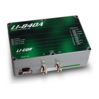
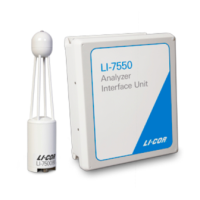
Connecting the Chamber to the Analyzer Control Unit
There are three hoses connected to the Survey Chambers; air to the chamber, air
returning from the chamber to the Analyzer Control Unit, and air that drives the
bellows. These hoses are connected to the side panel of the Analyzer Control Unit,
as shown in Figure 6-5. The Air In hose has a male fitting, and the Air Out hose
has a female fitting. Note that one of the hoses has a piece of black shrink wrap;
this hose attaches to the Air In fitting on the Analyzer Control Unit. The bellows
hose has a male fitting, and attaches to the port marked Bellows on the Analyzer
Control Unit. Insert the hoses until the fittings snap into place. To remove the
hoses, slide the collar on the fittings and pull straight out.