Initial Setup
2-13
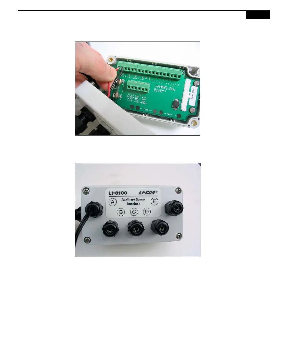
5. Pull lightly on the wires to remove excess wire from inside the interface,
re-attach the interface top cover, and tighten the gland cap.
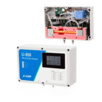
6. When you have finished installing all of your sensors and/or a power supply,
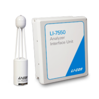
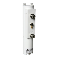
attach the Auxiliary Sensor Interface cable connector to the connector on the
side panel of the Analyzer Control Unit labeled Aux. Sensor Interface. The
Sensor Interface module has metal fittings on the back that snap into the
brackets above the side panel connectors for transporting the unit, as shown
below. NOTE: In order to achieve a weathertight seal and good electrical
connection, the interface cable connector must be tightened until it
completely covers the o-ring seal on the Analyzer Control Unit connector.