6-20
Using the 10 and 20 cm Survey Chambers
V2 Aux Input at voltage channel 2 (soil moisture).
V3 Aux Input at voltage channel 3 (soil moisture).
V4 Aux Input at voltage channel 4 (soil moisture).
T1 Aux Input at thermocouple channel 1, in degrees C.
T2 Aux Input at thermocouple channel 2, in degrees C.
T3 Aux Input at thermocouple channel 3, in degrees C.
T4 Aux Input at thermocouple channel 4, in degrees C.
Flux Computation Automatically computes flux rate after each
measurement.
GPS Latitude Decimal degrees, hemisphere (+) north or (-) south
GPS Longitude Decimal degrees, hemisphere (+) east or (-) west
GPS Status A = Valid position, V = NAV receiver warning
Speed Speed over ground, 0000.0 to 1851.8 km/h
GPS Course True course over ground, 000.0 to 359.9 degrees
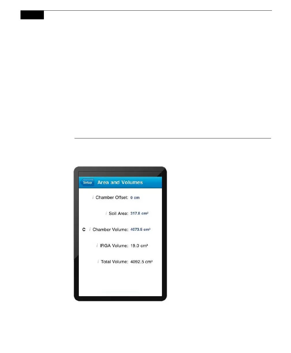
3. Click on the Setup menu and choose Areas and Volumes. The Areas,
Volumes, & Flow Rate screen appears (below).
The Total Volume value is
computed and displayed after
the Chamber Offset, Soil Area,
and Chamber Volume values are
entered. IRGA Volume is set
under “Instrument Settings” and
is displayed here.
Chamber Offset
The Chamber Offset is the distance (in cm) between the soil surface and the
top of the soil collar, and is dependent upon the depth that the collar is
inserted into the ground (discussed in Section 2, Initial Setup). The soil CO
2
flux measurement requires an accurate estimate of the Total System Volume.
 Loading...