3
6 LAN: Connect a CAT5 RJ45 Ethernet cable for local and remote connectivity.
7 RS485: Not
supported.
8 Ground
9 Power Port:
Connect the included power cable.
10 Power Switch: T
urns the NVR on / off.
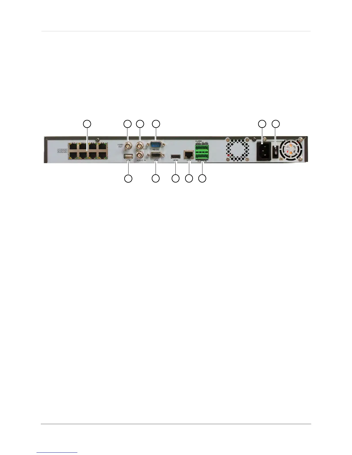
16-Channel
1 Camera In: Connect IP cameras 1~8. Integrated PoE (Power Over Ethernet) ports provide
power to cameras and video connection to NVR.
NOTE: To connect cameras 9~16, see “Connecting Camer
as over the Local Network” on page 9.
2 Video Out: Outpu
ts the live display to a secondary monitor using a BNC cable (not included).
NOTE: You cannot see the mouse or system menus via BNC. Use a BNC to RCA adapter (not
included) t
o connect the NVR to RCA inputs (i.e. for a TV connection).
3 Audio I
N/Audio OUT:
Connect a microphone (not included) and 1 audio output device (e.g.
speakers; not included).
4 RS-232:
Servic
e only; not supported.
5 Power Port:
Connect the included power cable.
6 Power Switch: T
urns the NVR on / off.
7 USB Port: Conn
ect a USB mouse (included) or USB flash drive (not included) for data backup
or firmware updates.
8 VGA
Port: Connect a V
GA monitor to view the system interface.
9 HDMI Port:
Connect an HDTV or monitor to view the system interface.
10 LAN: Connect a
CAT5 RJ45 Ethernet cable for local and remote connectivity.
11 RS485/Alarm: Not
supported.