LPKF Laser & Electronics AG | V. 1.0
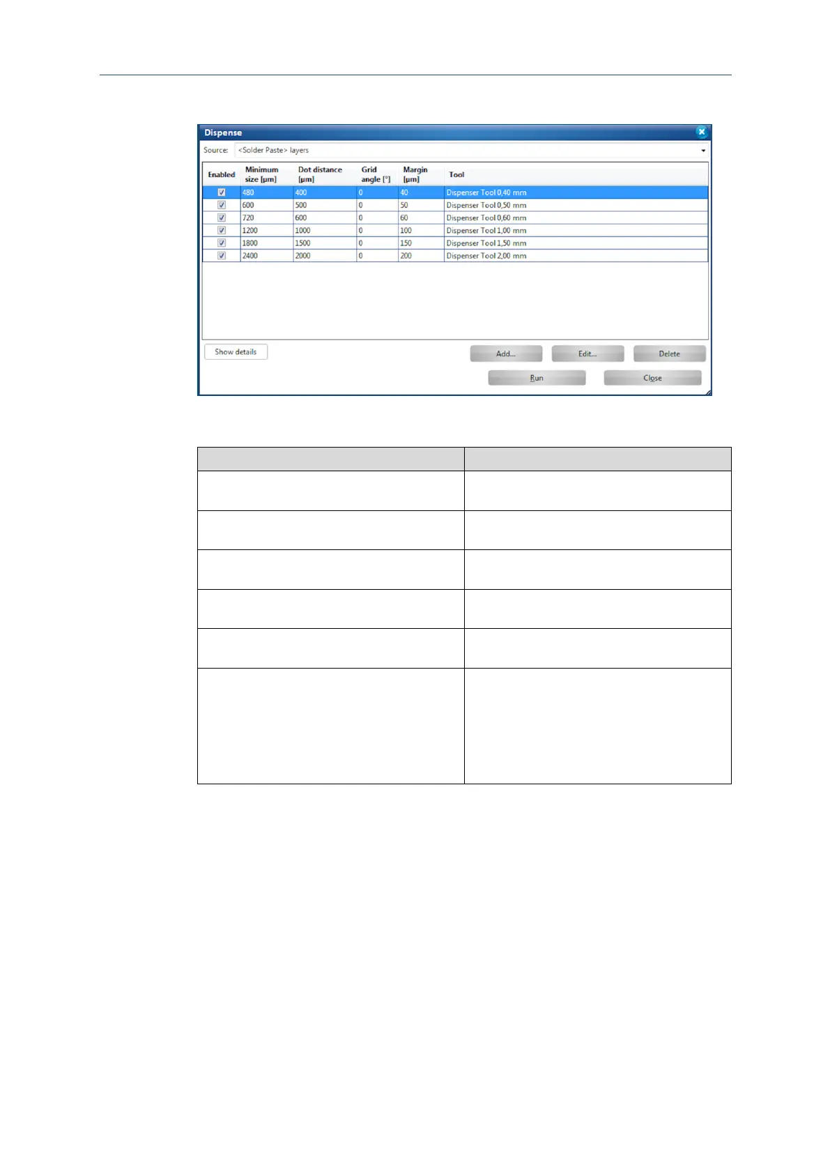
The following dialog is displayed:
Fig. 104: Dialog Dispense
The following table describes the functions of the columns:
Activates/Deactivates the corresponding
dispenser tool with a check mark.
Indicates the minimum pad size of the pads to
be filled in µm.
Indicates the distance between the individual
solder paste dots in µm.
Indicates the rotation of the solder-paste grid
on the pad.
Indicates the minimum distance of the solder-
paste dots to the edge of the pad in µm.
Indicates the corresponding dispenser tool.
The dispenser tools correspond to different
pad sizes that can be filled with the individual
tool. This is realized with the help of different
parameter sets. All dispenser tools use the
same dispenser as well as the same
dispenser needle.
Table 14: Settings in the dialog Dispense
12. Click on [Start].