V. 1.0 | LPKF Laser & Electronics AG
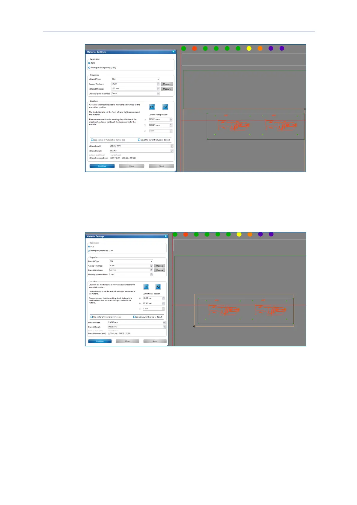
Fig. 88: Defining the right rear corner
The processing head moves to the right rear corner.
Click on [P2] in the dialog Material settings.
The material area is adapted.
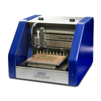
7. Click on the position of the screen that represents the front left corner of your
material:
Fig. 89: Defining the front left corner
The processing head moves to the front left corner.
8. Click on [P1]in the dialog Material settings.
The material area is adapted to the material.
9. Click on [OK].
The phase Placement is started.
The material settings have been defined.