LPKF Laser & Electronics AG | V. 1.0
The layout can be copied and placed freely on the base material for economic usage
of the PCB material depending on the size of the layout and the size of the base
material.
Placing the layout
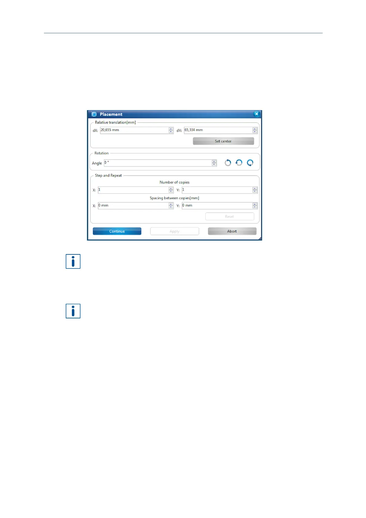
1. Enter the values for the desired position into the fields dX and dY. You can also
move the toolpaths in the machining view using the mouse.
Fig. 90: Dialog Placement
You can repeat the toolpaths in x and y direction by changing the values in the group
Step and Repeat.
2. Enter the value 2 in the field Y under Number of copies.
3. Enter the value 0 mm in the field X under Spacing between copies.
4. Enter the value 5 mm in the field Y under Spacing between copies.
The field Spacing automatically displays the value for the layout width. The desired
spacing between the layouts has to be added.
5. Click on [Apply].
The layout is copied in y direction.
6. Click on [Continue].
The phase DrillFiducial is started.
The layout has been placed.