OPERATING CONTROLS AND PROCEDURES 16000 OPERATOR MANUAL
3-50
Published 05-09-17, Control # 011-29
6. Pressure Test and Calibration Screen icon
The Menu screen operates on one level only.
• Use Select buttons to highlight icon that represents the
screen to be entered. Press the Enter button to go to
selected screen.
• To return to Menu screen, press Exit button until Menu
screen appears.
Information Screen
See Figure 3-37 for the following procedure.
Information screen shows all the general crane information
required for viewing during normal operation. The screens
contain three data boxes which may be individually tailored
to show the information items appropriate for the current
crane application.
The Information screen operates on three levels:
Level 1— Selected data box highlighted blue. Use Select
buttons to highlight the data box to change.
Level 2 — Selected data box highlighted red. Use Select
buttons to choose the information item to be shown in the
highlighted data box.
Level 3 — Selected data box highlighted green (if
applicable). Use Select buttons to alter the information
displayed in the highlighted data box.
The crane information items currently available (if equipped)
for the two smaller data boxes on the left side of the screen
are as follows:
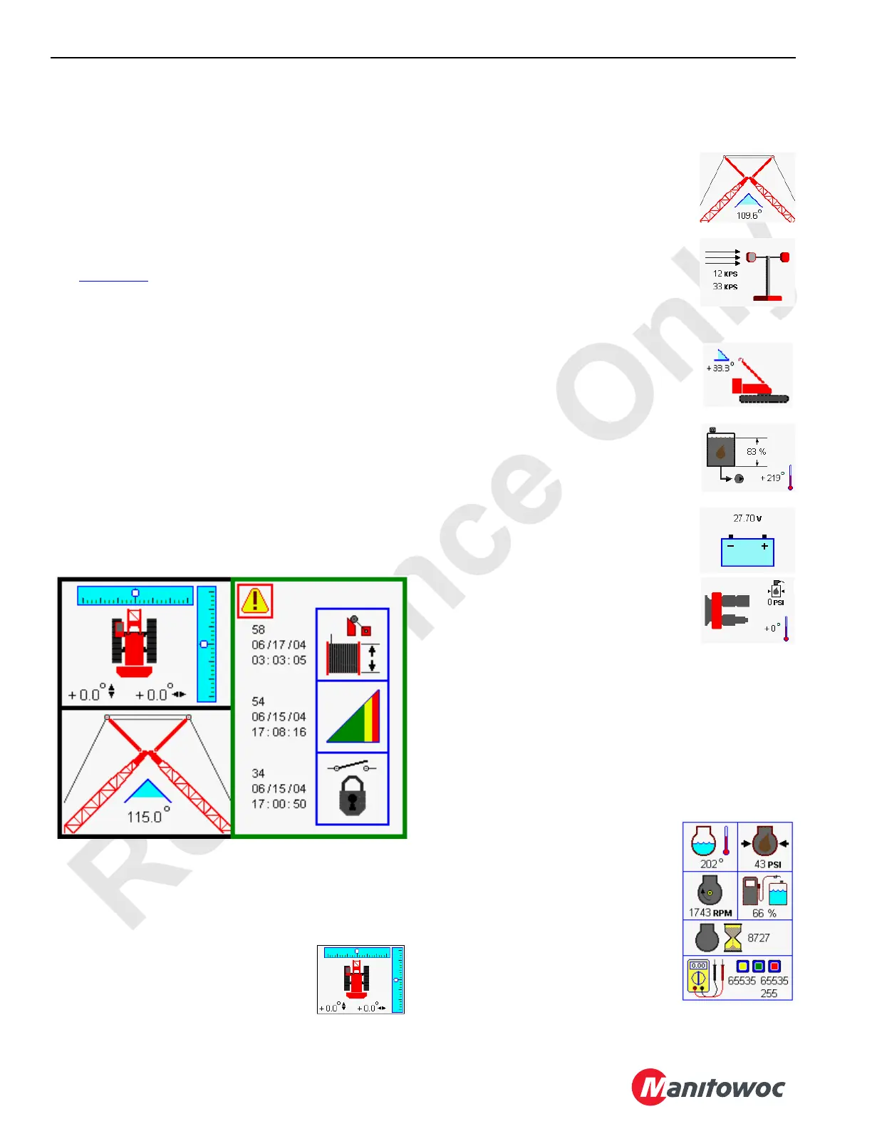
Crane Level
Crane level icon displays the crane level
condition forward to rear and side to side.
Unless otherwise specified in capacity
charts, all crane operations must be performed with crane
level to within one 1% of grade in all directions — 1 ft in 100 ft
(0,3 m in 30 m); or crane could tip.
Boom to Luffing Jib Working Angle
Boom to luffing jib icon displays the boom
to jib working angle between center line of
boom and center line of luffing jib.
Wind Speed Indicator
Wind speed icon displays the steady wind
speed and maximum gust wind speed. The
indicator is reset with Confirm button in
level 3.
Mast Angle
Mast angle icon displays the mast angle in
degrees mast is positioned above transport
position.
Hydraulic Tank
Hydraulic tank icon displays the tank fluid
level in percent and temperature in
degrees.
Battery
Battery icon displays the active battery
voltage.
Pump Drive
Pump drive icon displays the oil pressure
and temperature of pump drive cooling
system.
MAX-ER
®
Icons
MAX-ER
®
counterweight lift position and telescopic beam
extend icons are not shown. See MAX-ER
®
Operator
Manual for complete MAX-ER
®
attachment information.
The crane information items currently available (if equipped)
for the large data box on the right side of the screen are as
follows:
Engine
Engine data box displays the following
engine items:
• Engine coolant temperature should
be below 204
°F (96°C).
• Engine oil pressure should be
above 15 psi (1.03 bar).
• Engine speed in RPM, 1050 RPM
low idle 1,800 RPM high idle

 Loading...


