SET-UP AND INSTALLATION 16000 OPERATOR MANUAL
4-68
Published 05-09-17, Control # 011-29_v2
When slackness is noted, tightly wind the dead wraps of wire
rope onto the drum. If left uncorrected, a wedging action with
subsequent layers will occur, and the resultant abrasion may
cause broken wires in the dead wraps.
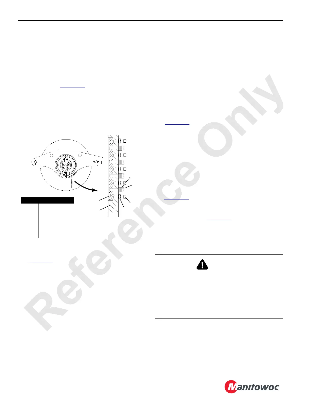
DRUM KICKER ADJUSTMENT
General
A drum kicker (see Figure 4-40) is provided on both flanges
of the main load drum (in boom butt) to improve wire rope
spooling for long boom lengths with small fleet angles where
the wire rope might stack up along either drum flange.
Observe the wire rope during initial break-in and periodically
during operation. If the rope stacks up at either end of the
drum, adjust the drum kickers.
Adjustment
See Figure 4-40 for the following procedure.
To move drum kickers (1) into the drum (take up space),
proceed as follows:
1. Remove drum guard from both ends of drum.
2. Remove an equal number of washers (3) from both
sides of kicker (1), one side at a time. Each washer
allows kicker to move 0.098 in (2,5 mm).
3. Loosely reinstall cap screws (2) and remaining washers
(3).
4. Loosen lock nuts (4) and adjust set screws (5) to move
kickers (1) into drum.
5. Repeat steps 1-3 only enough to improve spooling.
Moving drum kickers in too far can cause premature
wire rope wear.
6. Securely tighten set screws (5) and lock nuts (4).
7. Reinstall drum guards.
PAD EYE USAGE FOR WIRE ROPE
REEVING
See Figure 4-41 for the following procedure.
General
Some rotation-resistant wire rope supplied by Manitowoc is
equipped with a pad eye welded to the leading end of the
wire rope or to the button on the end of the wire rope.
A rigging line can be attached to the pad eye to make it
easier to reeve the load block.
Safety
1. Do not exceed approximate capacities listed in
Figure 4-41
.
2. Make sure rigging line and attaching hardware (clips and
rope connectors) are rated for the approximate
capacities shown in Figure 4-41
.
3. Inspect pad eye prior to each use. Replace it if:
• Any original dimensions have changed
• Cracks or breaks exist in metal or weld
1
2
3
4
5
6
FIGURE 4-40
Item Description
1 Drum Flange
2 Kicker
3 Cap Screw
4 Washers
5 Lock Nut
6Set Screw
WARNING
Flying Part Hazard!
Pad eye on end of wire rope has been provided for
reeving purposes only. Any other use is neither
intended nor approved.
Pad eye can break and fly apart with considerable force if
it is overloaded, not used properly, or not maintained
properly.

 Loading...


