Manitowoc Published 05-09-17, Control # 011-29 3-17
16000 OPERATOR MANUAL OPERATING CONTROLS AND PROCEDURES
B15. Fire Extinguisher
One fire extinguisher is in operator’s cab behind seat.
Foreign code requires another fire extinguisher be mounted
on the crane.
B16. Cab Door Brake
Manual handle for locking cab door in any position. Push
handle down to apply and pull up to release.
C – Indicators
See Figure 3-7 for indicators.
C1. Boom Angle Indicator
Shows the angle of the boom in degrees above horizontal.
The boom, luffing jib, and mast angles can be viewed on
RCL display or Main display.
See Figure 3-8
for identification of the various boom and
luffing jib angles.
C2. RCL Alarm (optional)
The amber beacon rotates and the alarm sounds whenever
the crane’s capacity is near an overload condition (when
RCL system is ON).
C3. Rear View Mirrors
Adjustable rear view mirrors on operator’s cab and right side
of rotating bed allow the operator to view rear of the crane.
Mirrors can be rotated inward for shipping.
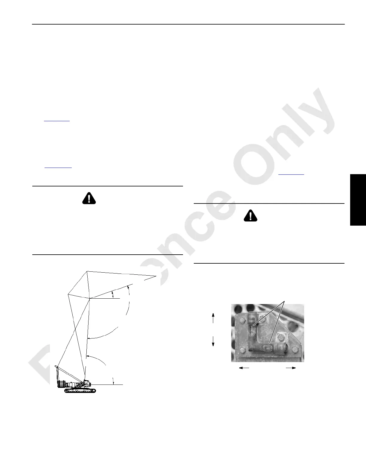
C4. Bubble Level
On past production cranes with upperworks jacking (S/N
16001032 and older), a bubble level is mounted on the cab
support.
On current production cranes (S/N 16001118 and newer), a
bubble level is mounted on the front of the carbody.
The bubble level indicates crane levelness from front to rear
and from side to side as shown in Figure 3-9
.
Crane levelness can also be viewed in the Information
Screen of the main display.
C5. Wind Speed Transmitter
Wind speed at the boom and jib points appears in the wind
speed screen (see Main display later in this section).
WARNING
Overload Hazard!
Use boom angle indicator only as a guide to position
boom near angle corresponding to radius for given load.
In all cases, radius must govern capacity. Exceeding
radius given in capacity chart can result in tipping or
structural damage.
FIGURE 3-8
Boom
Angle
Horizontal
A1298
Boom to
Jib Angle
Horizontal
Jib
Angle
C
L
Boom
C
L
Jib
WARNING
Tipping Hazard!
Unless otherwise specified on capacity chart, all crane
operations must be performed with the crane level to
within one percent of grade in all directions – 1 ft in 100 ft
(0,3 m in 30 m); otherwise, crane could tip.
FIGURE 3-9
P2102
Centered bubble indicates level.
One half of bubble off center
indicates approximately one
percent of grade out of level.
Side-to-Side
Levelness
Front-to-Rear
Levelness

 Loading...


