Manitowoc Published 05-09-17, Control # 011-29 3-59
16000 OPERATOR MANUAL OPERATING CONTROLS AND PROCEDURES
Function Mode Screens
See Figure 3-50 for the following procedure.
The Function Mode screens are used to enable/disable
modes and set operating parameter for the individual crane
functions. This screen operates on four levels.
Level 1— Image of overall crane shown. Use Select buttons
to highlight individual crane functions.
Level 2 — Shows the function mode screen for highlighted
crane function. The selected mode or limit data box is
highlighted blue. Use Select buttons to choose a mode or
limit data box.
Level 3 — The selected mode or limit data box highlighted
red. Use Select buttons to enable/disable a mode or to set a
limit.
Level 4 — The selected mode or limit data box highlighted
green. Use Select buttons to adjust the value shown in data
box.
To enable/disable modes or to set operating parameters for
the individual crane functions:
1. Press Enter or Exit buttons as required to go to level 1.
Use Select buttons to highlight desired crane function.
2. Press Enter button to go to level 2. Use Select buttons
to choose the mode or limit data box to access. Press
Enter button to go to level 3.
3. Use Select buttons to enable/disable mode or to adjust
operational parameter.
4. Press Enter button to go to level 4 if required. Use
Select buttons to adjust operational parameter.
5. Press the Exit button as required to return to a previous
level or to the Menu screen.
The yellow alert symbol is displayed if a system fault occurs.
See Information screen to access faults.
On (I) and off (0) icons in some data boxes
indicate and enable the electrical status of
item.
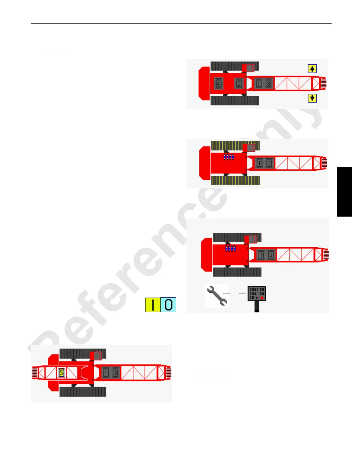
Drum Functions
Select drum functions 1 through 5 from screen shown below.
Swing Functions
Select swing functions from screen shown below.
Travel Functions
Select travel functions from screen shown below.
Setup Remote Functions
Select setup remote function from screen shown below.
MAX-ER
®
Functions
Select MAX-ER
®
functions from MAX-ER
®
attachment
screen. See MAX-ER
®
Operator Manual for complete MAX-
ER
®
attachment information.
Drum, Swing or Track Speed Limits
See Figure 3-54 in the following procedure.
Drum, swing, and crawler speeds can be selected. In level 3,
the value shown in these data boxes can be adjusted with
the Select buttons to limit the function speed between 25%
and 100% of maximum capability.
Diagnostic Screen
Accessory Items Selected
D16-18C
FIGURE 3-53
OR

 Loading...


