OPERATING CONTROLS AND PROCEDURES 16000 OPERATOR MANUAL
3-56
Published 05-09-17, Control # 011-29
Drum Diagnostic Screens
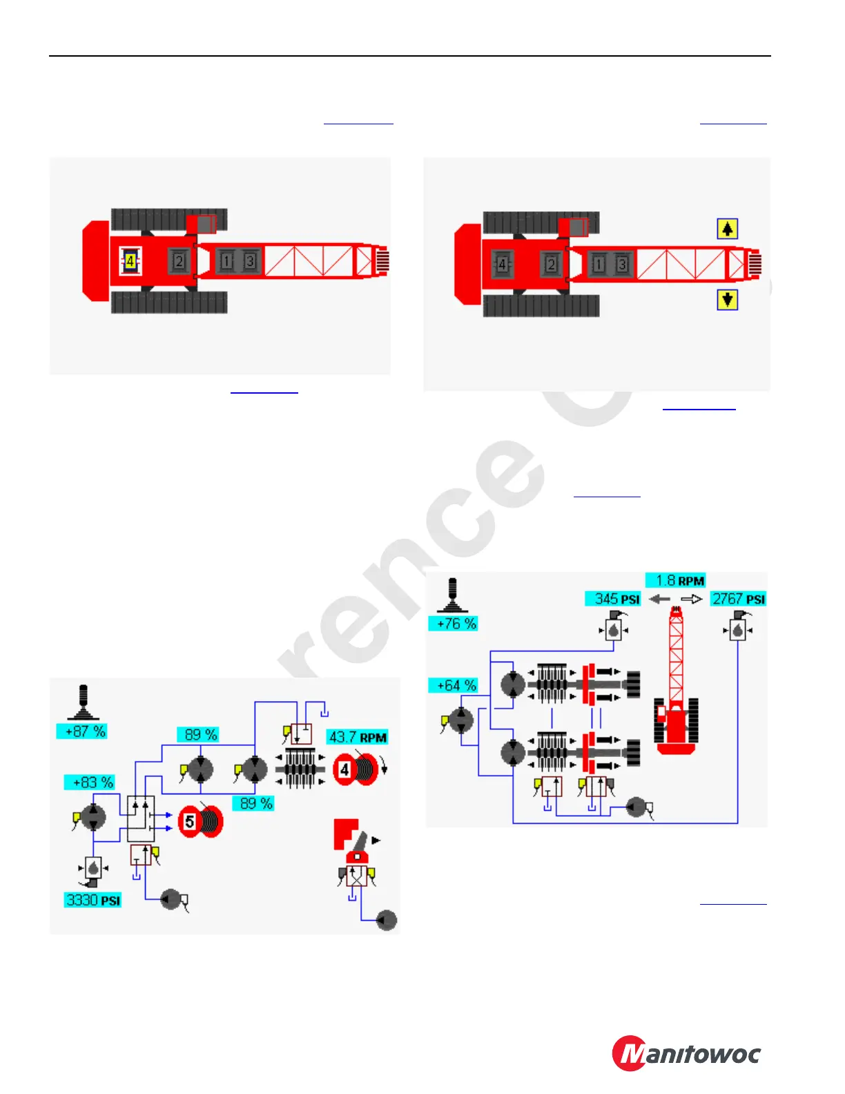
Select drum icon in screen level 1 as shown Figure 3-38.
Press Enter button to go to level 2
.
In the drum example shown in Figure 3-39, drum 4 function
is shown hoisting up. A single pump is shared with drum 5
and is connected to drum 4 through a diverting valve. A
second pump could also power drum 4 shown connected to
the left track through upper diverting valve.
NOTE: Mast hoist drum 5 is only selected when the crane
is configured with a MAX-ER
®
.
For load drums 1 or 2, drum 2 pump is dedicated to the drum
1 motor through diverting valve when drum 1 is selected. The
opposite is true when drum 2 is selected. Both drums can be
operated at the same time but would operate at one half
speed.
For load drum 3, the left travel pump is dedicated to operate
drum 3 motor through diverting valve when drum 3 is
selected. Drum 3 is inoperable when traveling. Drum 3 can
be configured as load drum or luffing jib.
Swing Diagnostic Screen
Select swing icon in screen level 1 as shown in Figure 3-40.
Press Enter button to go to
level 2.
Swing system icons are displayed in Figure 3-41. The
example shows how the swing function might appear when
swinging right. Circular arrow symbols near each pressure
sender indicate which sender monitors swing right and left
pressures.
NOTE: The example in Figure 3-41
is for past production
cranes with swing lock. See section one of the
service/maintenance manual for current production
swing diagnostic screen with swing lock removed.
Travel Diagnostic Screen
Select travel icon in screen level 1 as shown in Figure 3-42.
Press Enter button to go to
level 2.
FIGURE 3-38
Diagnostic Screen
Drum 4 Selected
D16-05
FIGURE 3-39
Drum 4 Selected
D16-06B
FIGURE 3-40
D16-07
Diagnostic Screen
Swing Selected
FIGURE 3-41
D16-08B
Swing Right
Selected

 Loading...


