Manitowoc Published 05-09-17, Control # 011-29 3-53
16000 OPERATOR MANUAL OPERATING CONTROLS AND PROCEDURES
Diagnostic Screen
Diagnostic screens show a graphic of hydraulic circuit and
status of all pumps, motors, valves, and switches that apply
to crane function selected.
This view-only screen operates on two levels:
Level 1— Image of overall crane shown. Use Select buttons
to highlight individual crane functions.
Level 2 — Shows Diagnostic screen for highlighted crane
functions.
The yellow alert symbol is displayed if a system fault occurs.
Go back to Information screen to identify the fault.
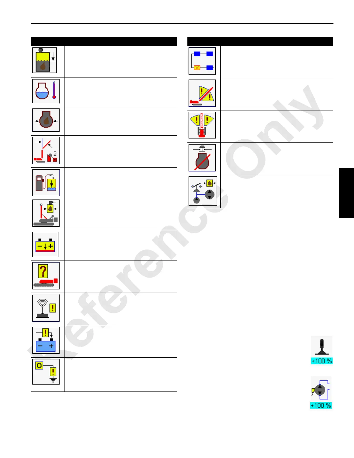
Diagnostic Screen Component Icons
Each Diagnostic screen component icon is identified and
described in the following paragraphs.
Control Handle
Displays system control handle command in
percent from neutral with +raise and –lower for
drums, +right and –left for swing, and +forward
and –reverse for travel.
Variable Closed-Loop Pump
Pump command from neutral (0%) to +/-% of full
displacement for drums, swing, and travel.
69-Hydraulic Reservoir Level— Hydraulic oil at
caution low level indicated on tank gauge. Fill
tank.
70-Engine Coolant Temperature — Engine
coolant temperature above 205°F (96°C).
71-Engine Oil Pressure — Oil pressure below
7.25 psi (0.5 bar).
73-Jib Maximum Up 2* — Limit switch stops
luffing jib when jib is raised to maximum angle.
Lower luffing jib. Cannot bypass this limit.
75-Low Fuel Level — Five percent fuel
remaining in tank. Fill tank as soon as possible
to prevent engine stoppage.
77-Mast System — Boom/mast hoist inoperable
in both directions. Determine cause of fault and
correct.
78-Battery Low — Battery voltage below 18
volts. Determine cause of fault and correct.
80-Invalid Configuration*— Make sure selected
RCL configuration for load drums is correct.
81-Wireless System — Wireless load link
sensing fault. See wireless link information in
separate Rated Capacity Indicator/Limiter
manual.
83-Alternator — Engine alternator is not
generating a charge to the battery.
84-Digital Output Disabled — Digital output
signal has a short circuit between computer
node and output device. See CAN Bus screen or
Diagnostic screen information to identify
problem component.
Item Description
85-CAN Communication — One or more
computer nodes are not communicating
correctly. See CAN Bus screen to identify
node(s).
86-Boom Range Limiter* — Up or down range
limiter is tripped. Move boom in direction away
from limit.
87-Swing Range Limiter* — Right or left range
limiter is tripped. Swing rotating bed in direction
away from limit.
88-Engine Shutdown* — Remote emergency
stop shut down switch is pushed. Pull switch up
to reset and allow engine to start.
89-Super Charge Pressure— Pressure switch
that monitors hydraulic fluid to main pumps is
open.
Item Description
 Loading...


