SET-UP AND INSTALLATION 16000 OPERATOR MANUAL
4-58
Published 05-09-17, Control # 011-29_v2
Install Load Line
See Load Block Reeving instructions for proper routing and
reeving of load lines.
Connect Boom Wiring
1. Install block-up limit components shown in Figure 4-32
and in Boom Wiring and Limits Electrical Drawing at the
end of this section.
2. Install wind speed indicator assembly if removed for
shipping. Use star washers to attach mounting bracket
to boom top to provide a good ground (see Wind Speed
Assembly drawing at the end of this section).
3. Connect electric cables from cable reel in boom butt to
node controller in boom butt and to wireless transceiver
in boom top (see Boom Wiring and Limits Electrical
Drawing at the end of this section).
4. Connect electric cables from block-up limit switches and
wind speed transmitters to proper receptacles on boom
and jib node controllers.
5. To protect electrical components:
a. Attach sealing caps to ends of all unused cables,
unused receptacles, and unused terminator plugs.
b. If equipped, attach terminator plugs to unused
receptacles.
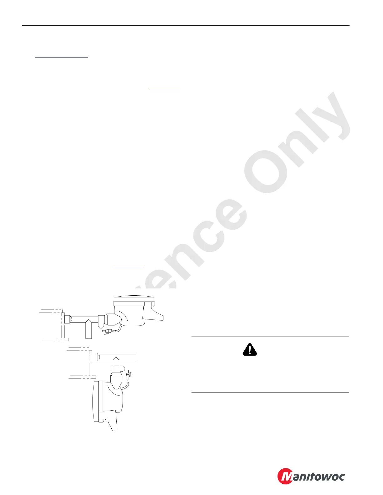
6. Remove optional boom light from shipping position tube
by loosening thumbscrew at base of light. Position on
working position tube (see Figure 4-31
) and tighten
thumbscrew to secure. Connect boom light to electrical
cable WCLE.
Perform Pre-Raising Checks
Perform following pre-raising checks and correct any defects
before raising boom.
Crane on firm, level surface.
Crawlers blocked if required per Capacity Chart.
All connecting pins installed and properly retained.
Boom inserts installed in proper sequence.
Boom straps installed in proper sequence.
All jib backstay straps, links, and pins removed from
boom sections (if luffing jib will not be used).
All insert and strap connecting pins installed and
properly retained.
Mast arms fully lowered.
Boom hoist wire rope spooled tightly onto drum and
engaged with proper sheaves. Wire rope securely
anchored to socket and wedge at mast.
Load lines spooled tightly onto drums and engaged with
proper sheaves. Load lines securely anchored to
sockets at boom points or at load block and weight ball.
All blocking, tools, and other items removed from boom.
Electronic boom angle indicator properly installed and
adjusted.
Block-up limit control properly installed and operational.
Rated Capacity Indicator/Limiter properly installed and
operational.
Proper capacity chart selected on configuration screen
of RCL display.
Automatic boom stop properly installed. Must be
adjusted after boom is raised.
Crane and attachment properly lubricated.
Wind within allowable limits for operation.
Boom Removal
Boom removal is the reverse of installation.
A16306_1b
Working Position
FIGURE 4-31
Shipping Position
A16306_1a
WARNING
Tipping Hazard!
Prevent the crane from tipping. Block ends of crawlers, if
required per capacity chart, before raising or lowering
boom from or to ground.

 Loading...


