Manitowoc Published 05-09-17, Control # 011-29_v2 4-51
16000 OPERATOR MANUAL SET-UP AND INSTALLATION
Connect Boom Straps
See Figure 4-26 for the following procedure.
The boom straps and links are shipped on the boom sections
as shown in View B.
1. Connect straps (1, View A) at top end of butt and each
insert as follows:
a. Remove pins (3, View B) and rotate links (4) to
working position (View A).
b. Pin links (4, View A) in working position.
c. Remove pin (5, View A) from end of each strap (1).
d. Rotate links (2a, View B) rearward and pin to
adjacent strap with pin (5, View A).
NOTE: If intermediate suspension is required (see Boom
Assembly Drawing), use links (2b, View C) in place
of links (2a, View A).
Store links (2a) on link (10, View C).
Install Intermediate Suspension
See Figure 4-26 and Figure 4-27 for the following procedure.
NOTE: Intermediate suspension is required at locations
specified in Boom Assembly Drawing.
1. If not already done, replace links (2a, View A) with links
(2b, View C).
See View C for the remaining steps.
2. If not already done, remove and store standard pin
(15a).
3. Using pin (15b), install link (14) and reconnect inserts.
4. Attach pendant (12) to link (14) with pin (13).
5. Connect pendant (12) and either adjustable link (8) or
pendant (7a or 7b) to link (10) with pin (11).
6. If adjustable link (8) is required, pin pendant (7a or 7b) to
adjustable link with pin (9).
Pin pendant to proper holes in adjustable link as
specified in Figure 4-27
.
7. Pin pendant (7a or 7b) to links (2b) with pin (6).
8. Repeat steps 1 – 7 on other side of insert.
When boom is raised, boom straps will lift intermediate
suspension into position and support inserts.
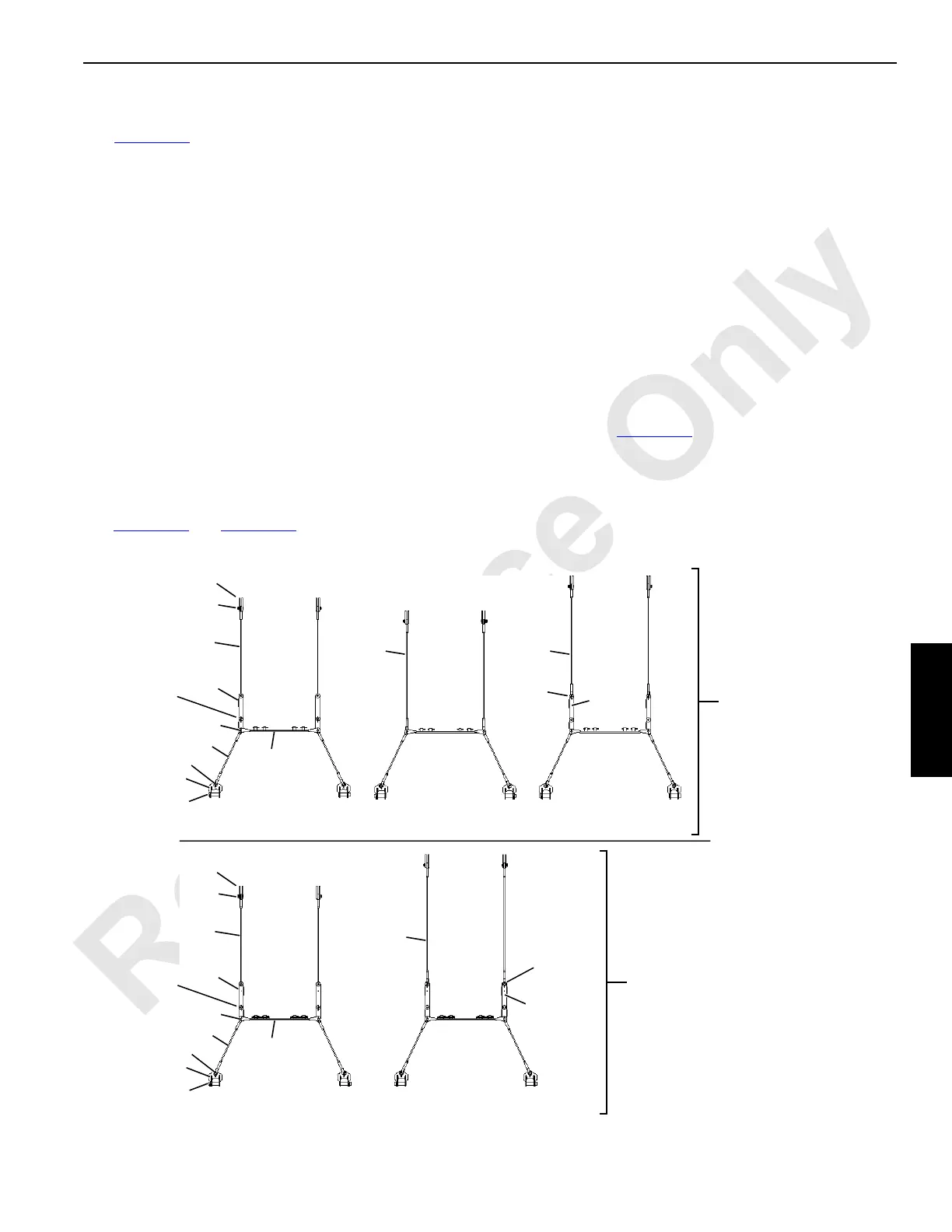
FIGURE 4-27
255.9 ft (78 m) and
314.9 ft (96 m) Boom
275.6 ft (84 m)
Boom
295.3 ft (90 m)
Boom
9
BOTTOM
Holes
Components are identical on
both sides of boom sections.
12
14
13
6
2b
7a
11
8
10
7a 7a
9
TOP
Holes
8
15b
A13137
255.9 ft (78 m) and
275.6 ft (84 m) Boom
9
BOTTOM
Holes
12
14
13
6
2b
7a
11
8
10
15b
295.3 ft (90 m)
Boom
Boom with Extended
Upper Boom Point
Boom Only or Boom
with Standard
Upper Boom Point
7b
9
TOP
Holes
8
NOTE: The intermediate suspension parts
are stored in the boom butt and in
the parts box supplied with the
crane.
 Loading...


