Manitowoc Published 05-09-17, Control # 011-29_v2 4-27
16000 OPERATOR MANUAL SET-UP AND INSTALLATION
Install Crane Counterweight
The crane counterweight must be installed with an assist
crane.
The mast can be fully lowered as shown Figure 4-17
or
forward of center as shown in Figure 4-18
.
See Figure 4-17
for the following procedure.
1. Uncoil handling pendants (3, View B) with adapter plates
(8, View B) from storage pockets in tray (1) and hook to
lifting slings from assist crane (View C).
2. Lift counterweight tray into position at rear of crane and
place tray on ground.
3. Connect hydraulic hoses from counterweight cylinders
to couplers (4, View A) on rear of rotating bed.
4. Disengage counterweight pins (6) with switch on remote
control. Pins will engage if switch is released.
5. Hoist, travel, boom, and swing as required with assist
crane to guide counterweight tray into position under
rear of rotating bed (View C).
6. Engage hooks (5, View D) in tray with hooks in rotating
bed and align connecting holes.
7. Release switch on remote control to engage counter-
weight pins (6, View D).
8. Lower counterweight until it is supported by pins
(pendants slacken).
9. Remove hitch pins (7, View E) from storage lugs and
install in ends of counterweight pins (6).
10. Unhook handling pendants and adapter plates from
lifting slings. Coil pendants and place adapter plates in
storage pockets (View B).
11. Coil hydraulic hoses on tray for storage.
12. Do not disconnect hydraulic hoses from couplers on
rotating bed. Due to thermal expansion, they could be
difficult to reconnect.
13. Stack required counterweight side boxes (2, View F) one
box at a time alternating from side to side.
• First box each side must be centered on tray.
• Lifting lugs and steps on each box center adjacent
box
• If your crane is luffing jib prepared, side box (2) with
lugs (5) must be installed on top of each stack
WARNING
Falling Load Hazard!
Pendants are designed to handle counterweight tray only.
Do not attempt to lift tray with counterweight boxes
installed. Pendants could break allowing counterweight
tray and boxes to fall.
1
2
A10787-1
View F
(from rear)
View G
Luffing Jib Prepared
6
5
2
7
3
4
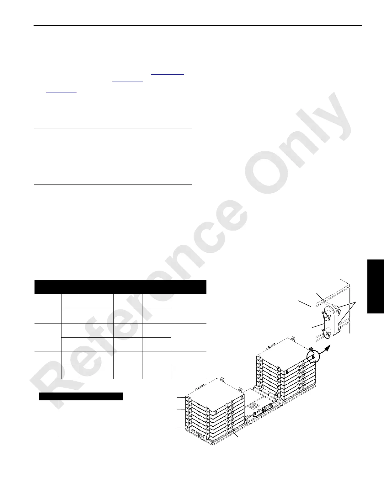
FIGURE 4-17 continued
Crane Counterweight Identification
Item Description
Total
Required
Weight
lbs (kg)
Total Weight
lbs (kg)
Series 1
1Tray 1
44,000
(19 958)
224,000
(101 605)
2Side Box 10
18,000
(8 165)
Series 2
1Tray 1
44,000
(19 958)
296,000
(134 265)
2Side Box 14
18,000
(8 165)
Series 3
1Tray 1
44,000
(19 958)
332,000
(150 595)
2Side Box 16
18,000
(8 165)
A10787-1
Item Description
3 Lifting Lug (4 each box)
4 Step (2 each box)
5 Lug (4 each top box)
6 Link (8, one top box)
7 Pin (4, one top box)
 Loading...


