Manitowoc Published 05-09-17, Control # 011-29 3-57
16000 OPERATOR MANUAL OPERATING CONTROLS AND PROCEDURES
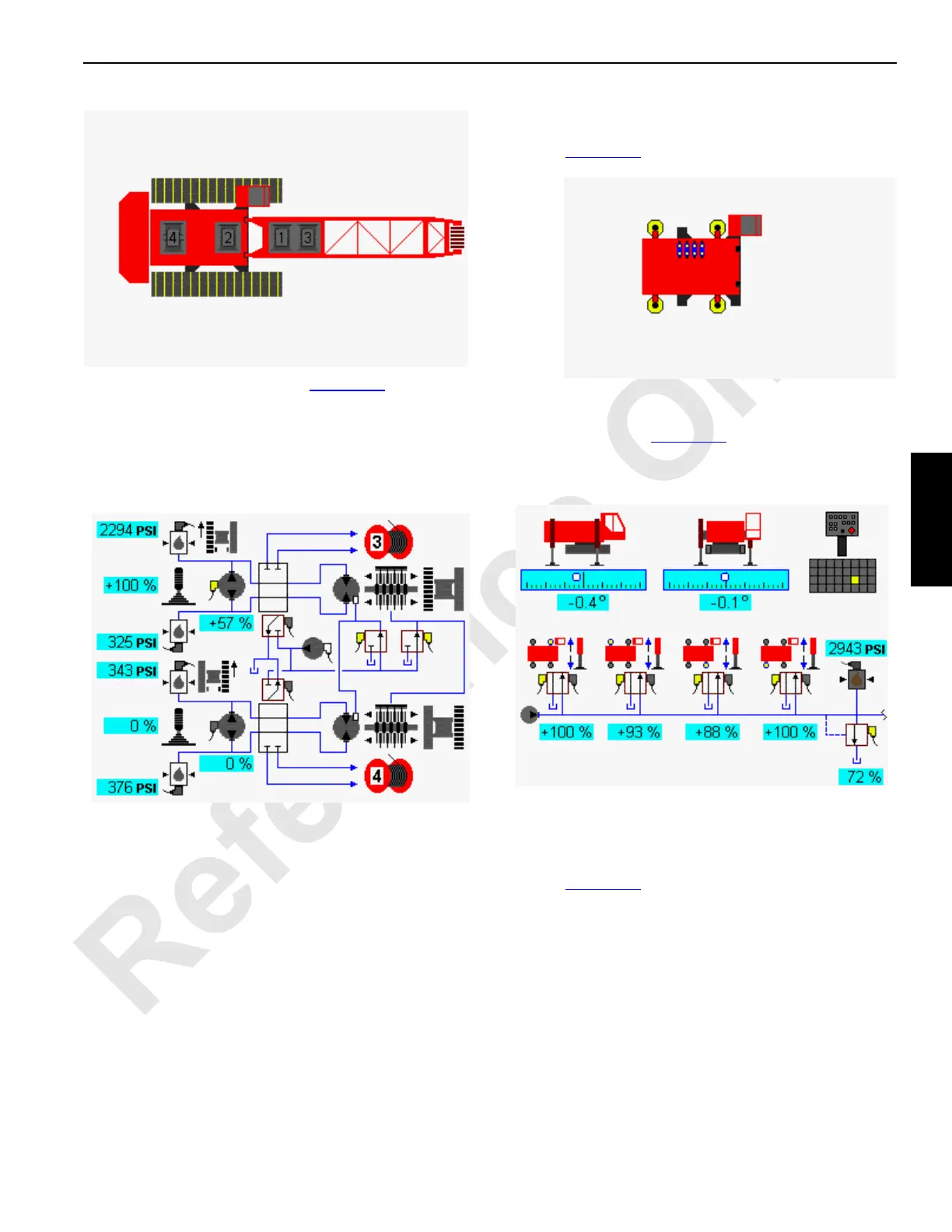
In travel system example shown in Figure 3-43, the left travel
pump is dedicated to operate drum 3 through diverting valve
if drum 3 is selected. The right travel pump is dedicated to
operate drum 4 through diverting valve if drum 4 is selected
under certain conditions when drum 5 is also configured.
NOTE: When crane travel is enabled, drum 3 is disabled.
Jacking Accessory Diagnostic Screen
Select crane carbody with jacking icon in screen level 1 as
shown in Figure 3-44
. Press Enter button to go to level 2.
At jacking accessory diagnostic screen component icons are
displayed as shown in Figure 3-45
. In the following example,
all jack switch on wireless remote is selected. The crane on
jacks icons indicate crane level status.
Pins and Fan Accessory Diagnostic Screen
Select crane, pins, and engine fan icon in screen level 1 as
shown in Figure 3-46
. Press Enter button to go to level 2.
D16-09
Diagnostic Screen
Travel Selected
FIGURE 3-42
FIGURE 3-43
D16-10B
Left Travel Selected
D16-11
Diagnostic Screen
Accessory Jacking Selected
FIGURE 3-44
FIGURE 3-45
Accessory Jacking
(Jacking All Selected)
D16-12

 Loading...


