OPERATING CONTROLS AND PROCEDURES RT9150E OPERATOR MANUAL
3-26
Published 2-23-2017, Control # 644-00
15
Power Units
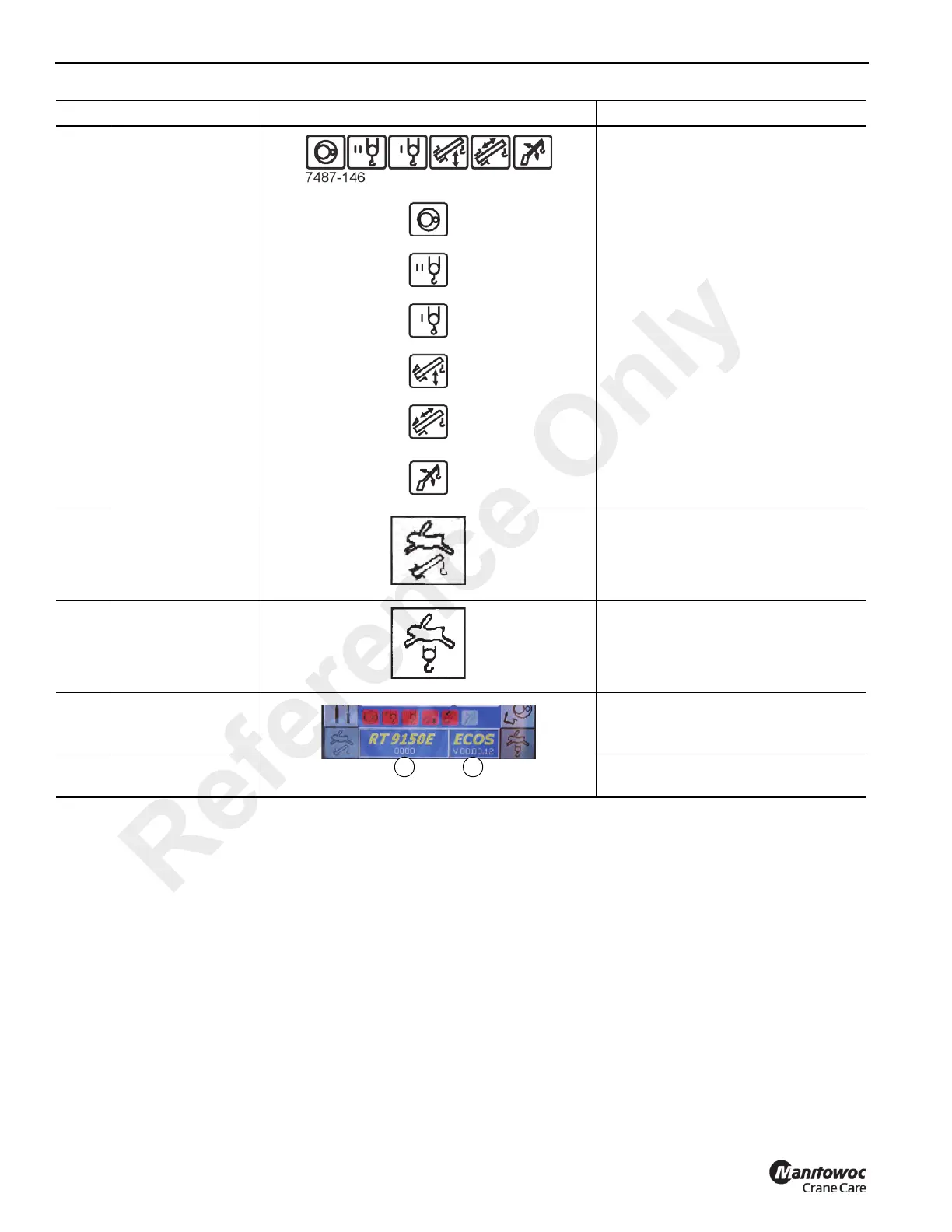
Display
The Power Units Display consists of
six icons that indicate when the
associated function is active.
Swing Gear
• Green: Swing gear on
• Red: Swing gear off
Auxiliary Hoist
• Green: Auxiliary hoist on
• Red: Auxiliary hoist off
Main Hoist
• Green: Main hoist on
• Red: Main hoist off
Lift Cylinder
• Green: Lift cylinder on
• Red: Lift cylinder off
Telescope
Cylinder
• Green: Telescoping mechanism on
• Red: Telescoping mechanism off
Raise/Lower
Luffing Jib
(Optional)
• Green: Luffing cylinder on
• Red: Luffing cylinder off
16
High speed lift/
telescope
Switch located on top of left-hand
joystick controller.
Gray: High speed off
Yellow: High speed engaged.
17
High speed hoist
(Main or Auxiliary)
Switch located on top of right-hand
joystick controller.
Gray: High speed off
Yellow: High speed engaged.
18
Serial Number
Display
(1) Shows the serial number which is
on the name plate on the
superstructure.
19
Program Version
Display
(2) Shows the current ECOS program
version.
Item Description Graphic Explanation
Reference Only