OPERATING CONTROLS AND PROCEDURES RT9150E OPERATOR MANUAL
3-82
Published 2-23-2017, Control # 644-00
Counterweight
Press the F5 or F6 button (4) or (5) repeatedly until the
display (2) shows the rigged counterweight version:
(4) Larger versions,
(5) Smaller versions.
The display (7) indicates the corresponding RCL code, the
symbol (6) indicates the RCL code is being determined.
The display (3) indicates the maximum load for the displayed
rigging mode and the displayed reeving.
You can cancel the input at any time. Press the button.
The main menu opens.
After the selection procedure, there are three options:
• Switching off the input mode:
Press the F1 button (1) (Figure 3-80) once, symbol
turns grey.
• Switching the input mode:
Press the button for the next component once, for
example, the F2 button (2), the symbol turns green.
• Accept the displayed rigging mode. Refer to Approve the
Rigging Mode, page 3-84.
Enter the other components of the current rigging mode in
the same way.
Boom System
For more information about using a boom extension refer to,
Boom Extensions, page 3-155.
1. Press the button (4) (Figure 3-81) repeatedly until the
symbol for the required input is green.
(1) Boom system entry
(2) Boom extension length/angle input
2. Press the button (3) repeatedly until:
- the display (5) shows the rigged boom system,
e.g. the boom extension
or
- until the display (6) shows the rigged boom
extension length, and in the case of a luffing
boom extension, the rigged boom extension
angle.
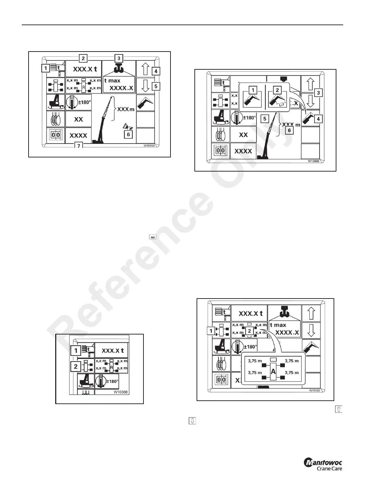
Outrigger Deployment
Refer to Figure 3-82.
With symbol (1) green, function ON. Press the buttons
to select:
- 100%, fully extended
Reference Only
 Loading...


