OPERATING CONTROLS AND PROCEDURES RT9150E OPERATOR MANUAL
3-140
Published 2-23-2017, Control # 644-00
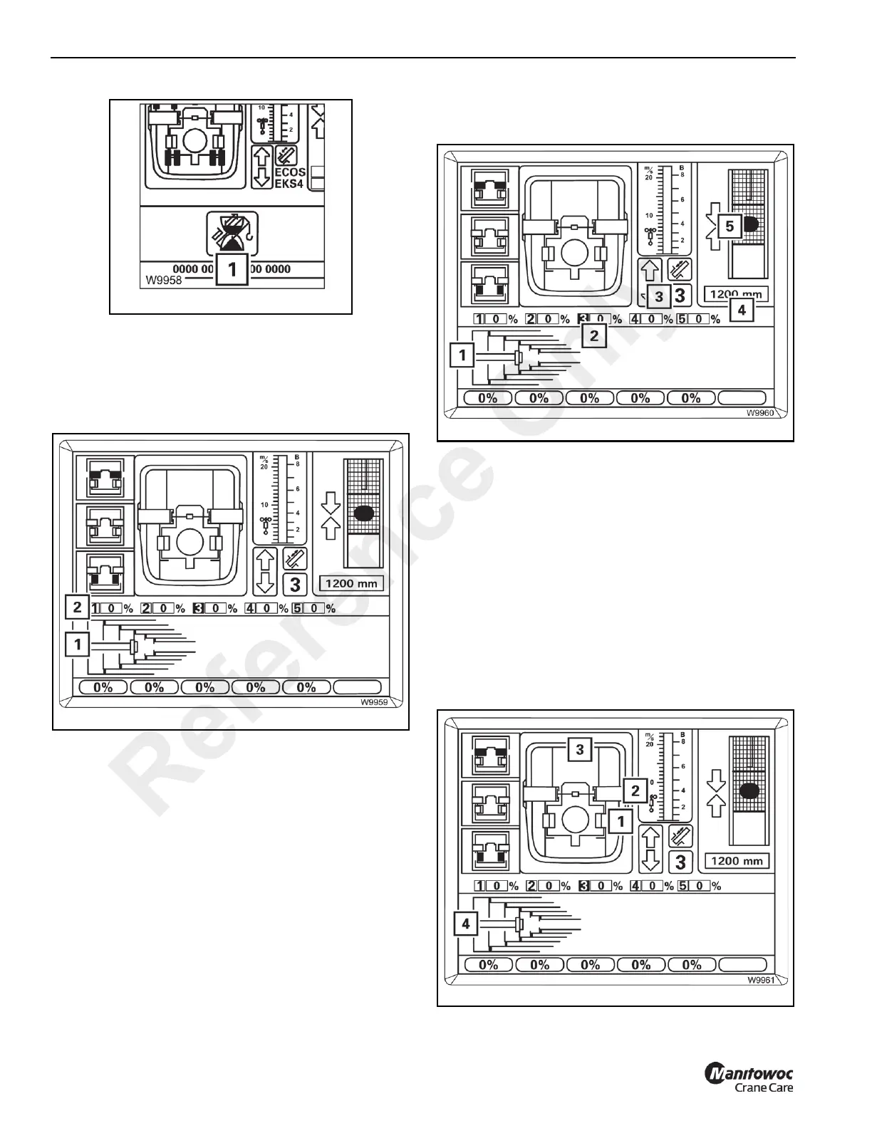
If an “error” display (1) (Figure 3-152) is pending, all
operating elements are disabled, refer to Telescope
Mechanism Error Messages, page 3-37
Current Telescope Status
Refer to Figure 3-153.
The display (2) shows the current telescoping in percent for
each telescopic section.
The display (1) shows the current telescope diagram.
Position of the Telescope Cylinder
Refer to Figure 3-154.
The display (4) shows how far the telescope cylinder is
extended, e.g. 1,200 mm (3.93 ft).
If the telescope cylinder is near a locking point:
• The display (3) shows the corresponding telescopic
section, e.g. telescopic section 3,
• the display (2) shows the corresponding telescopic
section number in green,
• the display (5) shows one or two arrows, depending on
the distance to the locking point.
The display (1) shows a top view of the current position.
Position of the Locking Pins
Refer to Figure 3-155.
Reference Only
 Loading...


