3-141
RT9150E OPERATOR MANUAL OPERATING CONTROLS AND PROCEDURES
Published 2-23-2017, Control # 644-00
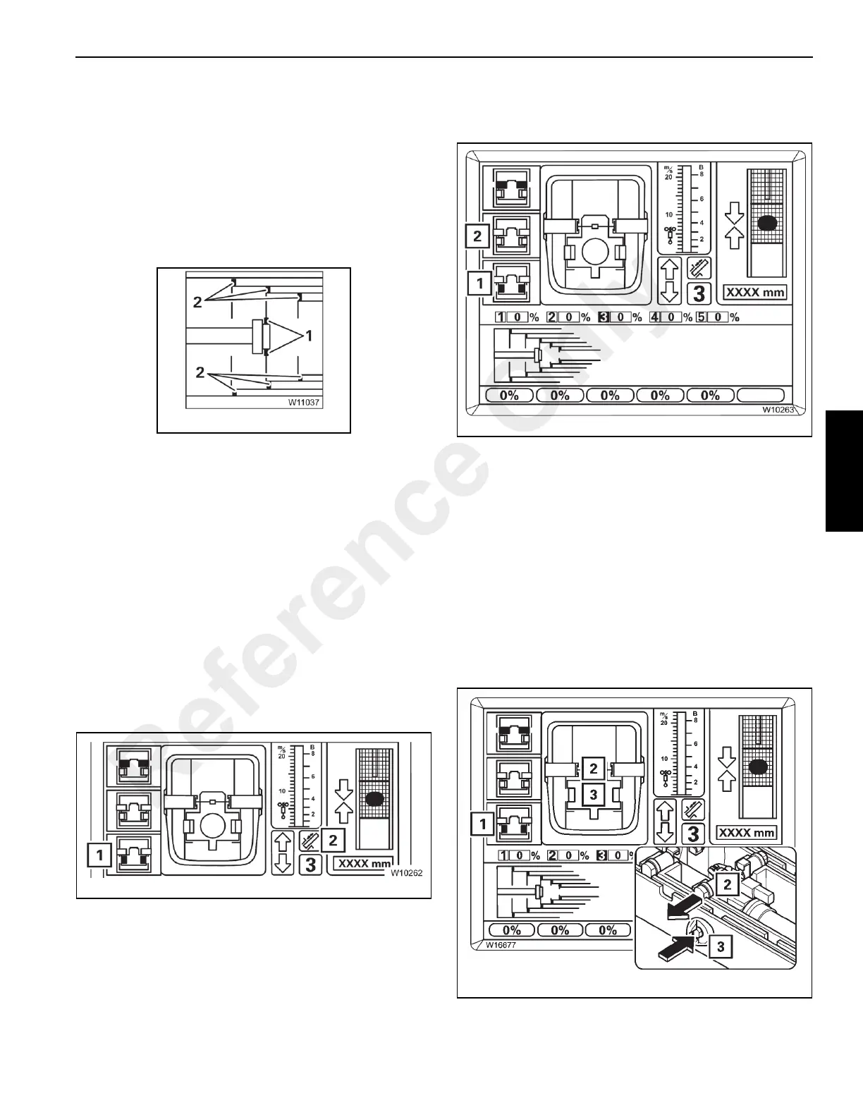
The display (3) shows the current positions of the locking
pins:
(1) the telescope cylinder pins,
(2) the telescopic section pins.
The current status of the pins are indicated by color:
Red: Unlocked
Green: Locked
Yellow: Intermediate position.
The display (4) shows the same positions as detailed in
Figure 3-156:
• (1) Locking pins on the telescope cylinder
• (2) Locking pins on the telescopic sections
Green: Locked
No display: Unlocked or intermediate position.
Unlocking the Telescope Cylinder
Unlocking the telescope cylinder is required for the cylinder
to be moved separately without telescopic section.
NOTE: The telescope cylinder and the telescopic section
cannot be unlocked simultaneously.
Prerequisites
Refer to Figure 3-157.
The following conditions must be met to unlock the telescope
cylinder:
• The telescoping mechanism must be on, symbol (2)
green,
• the telescope cylinder must be locked, symbol (1) grey.
To Select Unlock
Refer to Figure 3-158.
Press the F3 button (1) once.
• If the telescopic section is locked, symbol (1) flashes
indicating the telescope cylinder can be unlocked with
the control lever.
• If the telescopic section is unlocked, symbol (2) flashes
indicating that when the control lever is actuated the
telescopic section will lock and the telescope cylinder
will unlock.
NOTE: In the next step, both selections are carried out one
directly after the other.
Unlocking the Telescoping Cylinder
Refer to Figure 3-159.
Reference Only
 Loading...


