SET-UP AND INSTALLATION RT9150E OPERATOR MANUAL
4-30
Published 2-23-2017, Control # 644-00
6. Using the tag line, pull the front of the extension until the
extension mounting lugs (2) (Figure 4-38) align with the
boom head lugs (1).
7. Using a ladder or suitable lifting device, remove the
retainer clips (3) and pull the pins (4) out of the holders
(5). Install the pins through the connecting lugs and
secure with the retainer clips.
8. Have a helper hold, or make secure, the front of the
extension against the main boom.
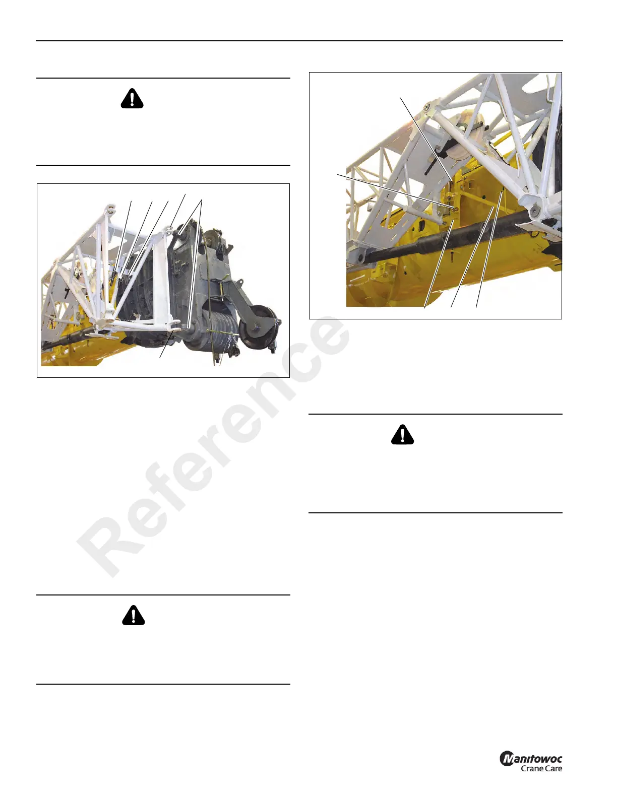
9. Using a ladder or aerial work platform, use the jib
extension pole, located in the cab, to pull the retaining
clip out of the horizontal locking pin (1) (Figure 4-39).
10. Use the jib extension pole to pull the horizontal locking
pin out of the front latch assembly and place in the
storage lug (2). Secure with the retaining clip.
11. Using the jib extension pole, disengage the front latch
assembly by pushing handle (3) (Figure 4-39) up and
onto the handle rest (4).
12. While maintaining control of the extension with the tag
line, remove the tag line from the bracket (4)
(Figure 4-37) on the main boom.
13. Use the tag line to pull the extension off the ramp.
14. While maintaining control with the tag line, swing
extension into position on boom nose.
NOTE: If the extension doesn’t easily swing around to the
front, slightly lower the boom from horizontal.
15. Using a ladder or suitable lifting device, remove the
retainer clips and pull the pins out of the holders (1)
(Figure 4-35). Install the pins (2) into the connecting lugs
(3). Secure with the retainer clips.
NOTE: If the pins cannot be inserted, the strain can be
taken off the connecting lugs, refer to, Relieving the
Load on Connecting Lugs, page 4-26.
CAUTION
Falling Objects Hazard!
Ensure the extension connecting pins are always secured
with retaining clips. This prevents unsecured pins from
becoming loose and falling out causing injuries.
DANGER
Crushing Hazard!
To prevent serious injury or death, do not release the front
latch without the extension being secured with a tag line at
the other end.
WARNING
Crushing Hazard!
To prevent serious injury or death, do not stand in the
swing arch of the extension. Be aware that if the boom is
lowered the extension will swing out on its own if not
secured with the tag line.
FIGURE 4-39
7567-8
1
2
3
Front Latch Assembly
4
Reference Only