4-41
RT9150E OPERATOR MANUAL SET-UP AND INSTALLATION
Published 2-23-2017, Control # 644-00
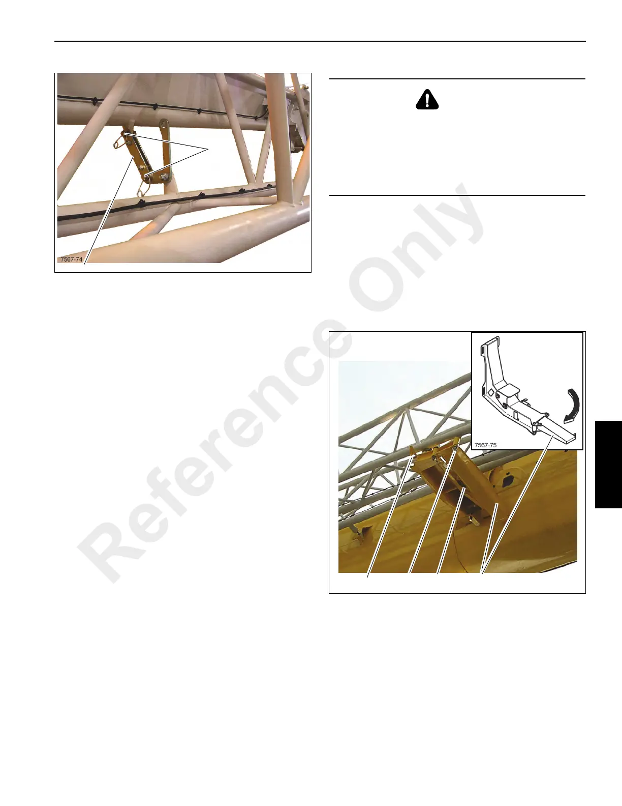
5. Secure the 23 ft (7 m) extension to the 36 ft (11 m)
extension with the locking bar (1) (Figure 4-59) and pins
(2).
6. Secure the pins with the retaining clips.
NOTE: If the 23 ft (7 m) extension is being stowed on the
main boom and the 36 ft (11 m) extension will
continue to be used, follow the next procedure for
stowing the 59 ft (18 m) extension in order to attach
the 23 ft (7 m) extension onto the main boom. Then
refer to The main boom is completely retracted and
has been lowered into a horizontal position., page
4-26 to deploy the 36 ft extension.
Stowing Procedure: 59 ft (18 m) Extension
In order to stow the 59 ft extension first perform the previous
procedure to stow the 23 ft (7 m) extension onto the 36 ft (11
m) extension.
Before stowing the extension ensure all electrical and
hydraulic lines are disconnected.
1. Lower the boom and attach a tag line to the front of the
36 ft (11 m) section and route the tag line back to the
nose of the main boom and secure it there to prevent the
extension from swinging around.
2. Release the retaining pin (1) and fold out the run-up
ramp (2) until the locking pin (3) engages in the lug (4)
(Figure 4-60).
DANGER
Crushing Hazard!
Ensure the extension is pinned to the front of the main
boom or is secured against swinging around.
This will prevent the extension from swinging
inadvertently to the side of the main boom, causing
severe injury or death.
Reference Only
 Loading...


