3D Scanning Technology Overview
F6 SMART™ – Volumetric Handheld Camera – User Guide
The F6 SMART™ Camera has one socket (the power and communication connector) that
allows users to either connect it to a USB 3.0 port of the workstation, or charge its
battery by using a Power-Supply / Charger source.
The scanned images are stored on the workstation.
To operate the system, the F6 SMART™ Camera must be connected, via a USB 2.0 cable,
to a Windows-based workstation, on which the Echo™ application software is installed.
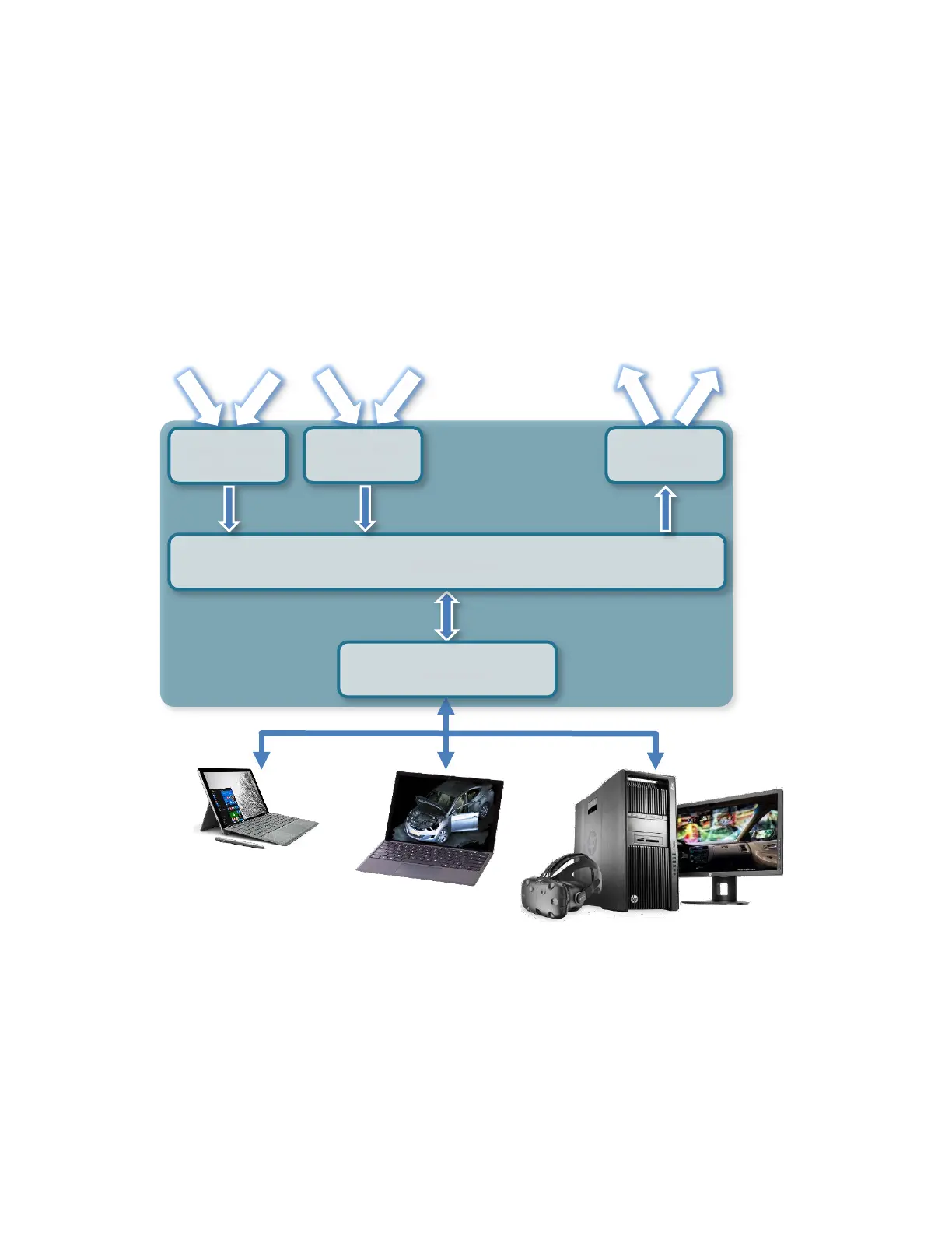
F6 SMART™ System Dataflow
Windows™ OS Devices
Figure 3 – F6 SMART™ System Dataflow
During acquisition, the video streams are recorded and processed on the workstation
while each video frame is decoded in real-time into a dense, color point-cloud of the
three-dimensional distance measurements (~ 60,000 points of data per frame). The
software automatically registers (aligns) the frames in the 3D video to recreate the 3D
geometry of the scene and its color information.
Projector
Driving Board
USB 2.0 Port