INSTALLATION 3 - 5
D-MAXE with OI-B/OI-Nwww.maxcessintl.com MI 2-296 1 D
Montage.fm
Mechanical fastening of
D-MAX operator interface
OI-B or OI-N
– Panel mount installation (see
figure 3.6
) or
– With an assembly bracket (optional) for wall mounting (see
figure 3.3
)
Note:
If a plug-in unit is present on the operator interface on the X7
connection, it may not be possible to push the operator inter-
face through the cut-out in the switch panel.
If this happens, follow these steps:
∙ Loosen the fastening screws on the plug-in unit with a TORX
8 screwdriver
∙ Carefully pull the plug-in unit out of the shaft by the
fastening screws
∙ Insert the operator interface into the switch panel cut-out
and assemble it with the fastening material
∙ Carefully insert the plug-in unit back into the shaft
∙ Tighten the mounting screws with the TORX 8 screwdriver. A
tightening torque of 0.25 Nm is recommended
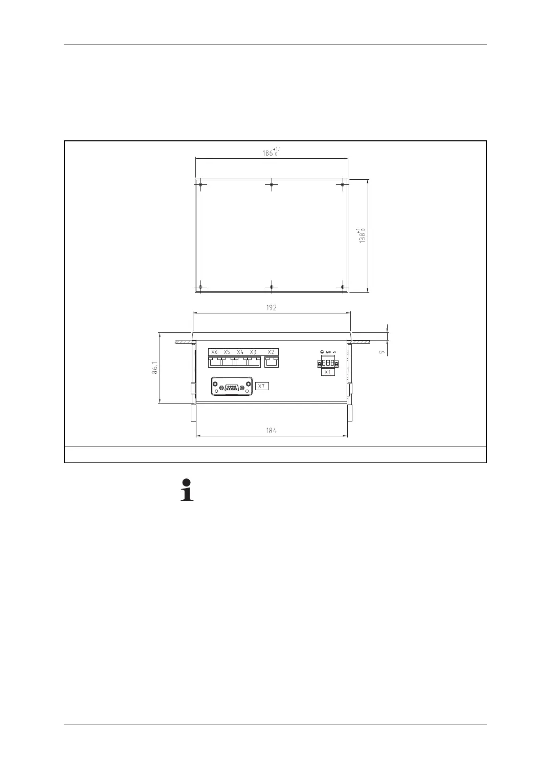
Figure 3.4: Dimensions of the D-MAX operator interface for panel installation and switch panel cut-out