OPERATION 4 - 2
D-MAXE with OI-B/OI-Nwww.maxcessintl.com MI 2-296 1 D
Bedienung.fm
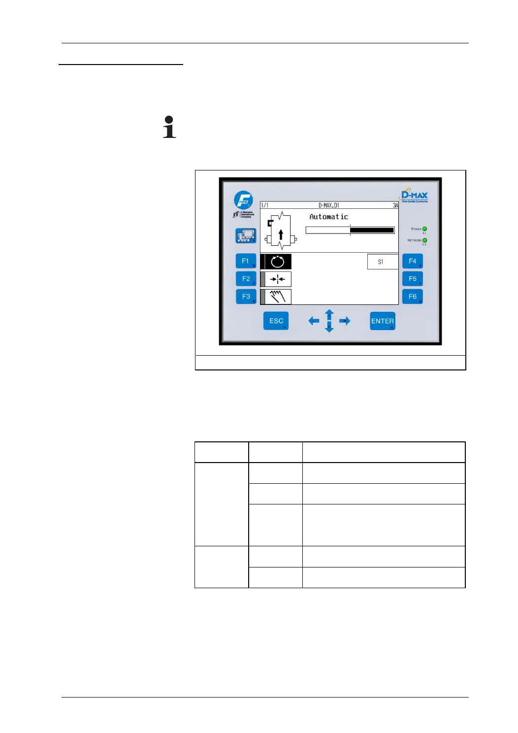
User interface The structure of the D-MAX operator interface's user interface is
shown in
Figure 4.1
. The D-MAX operator interface consists of
13 keys, a green display and LED displays.
Note:
The user interface described below applies to OI-B and OI-N
operator interfaces as well as the virtual operator interfaces.
LED displays on the operator
interface OI
* not present on virtual operator interface
Additional information about error messages that are displayed
may be found in Section
Troubleshooting, page 10-1
.
Figure 4.1: User interface
LED Status Indicates
L1*
Power
Off No power supply.
Green Power supply and temperature OK
Green
flashing
Power supply voltage to low,
internal voltage outside tolerance or
internal temperature too high
L2*
Network
Off No connection
Green Ethernet connection detected